Working on a project that uses the maestro 12 channel servo controller. I know it has one available PWM channel which means I should be able to use it to drive a DC motor controller that accepts PWM.
I think this one will work: https://www.pololu.com/product/2960/specs
Am I correct that I would use the PWM channel as the throttle for the motor controller AND have to use an additional channel on the Maestro with an RC switch to act as the direction change for the GIOP input on the motor controller?
When I looked at the wiring diagram for the controller it looks like it needs two PWM lines or one PWM and one GIOP to tell it forward or reverse.
Does this all check out? Trying to get it some everything can be controlled via the Pololu Maestro Command Center.
Thanks!
Hello.
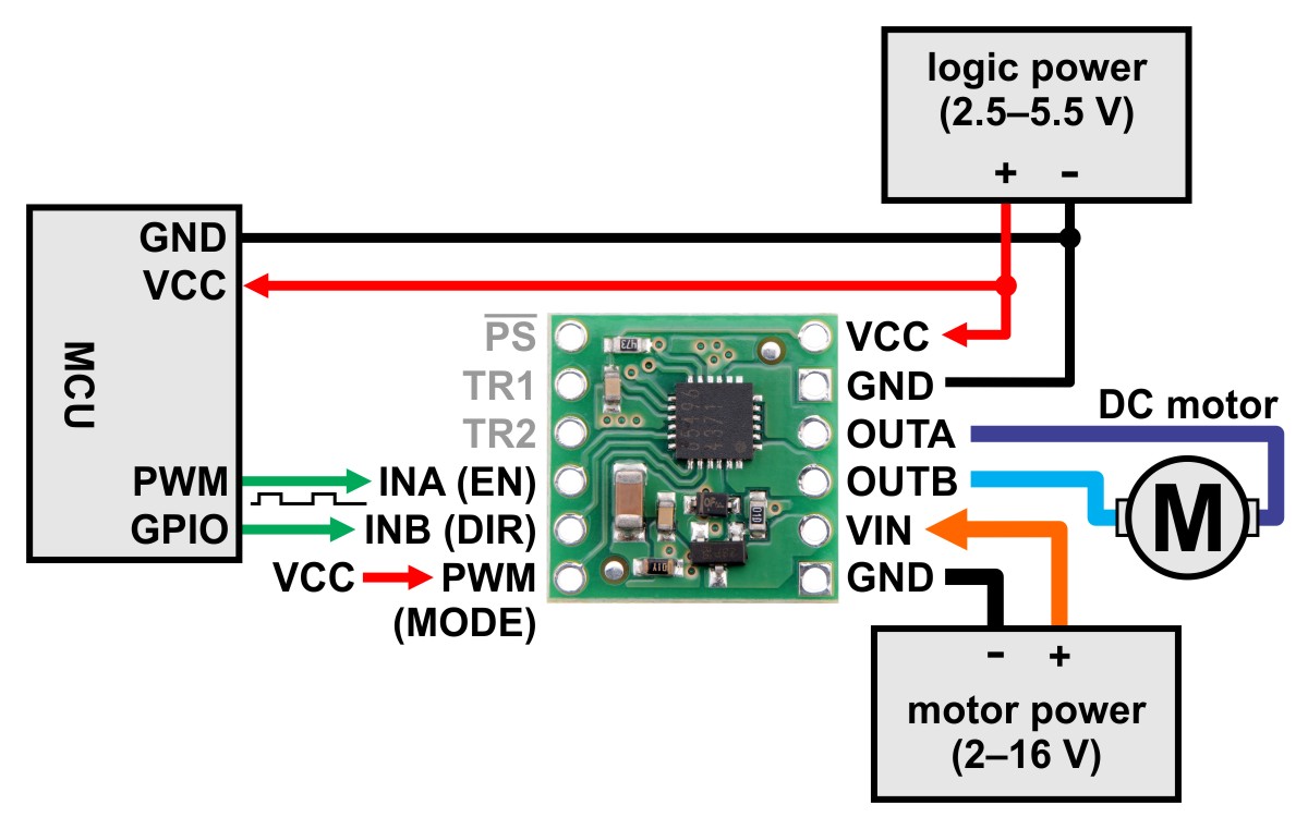
You can control the #2960 BD65496MUV motor driver carrier using 2 channels on the Mini Maestro: one for the PWM signal and one for direction, connected to the INA(EN) and INB(DIR) pins respectively. You do not need the RC switch for this. Instead, you can just configure the Maestro channel you are using for the direction as an “output” under the Channel Settings tab of the Maestro Control Center. You can read more about the “Output” mode of a Maestro channel in the “Channel Settings” section of the Maestro user’s guide.
Please note you will need to tie the PWM (mode) pin on the BD65496MUV carrier high (which you can do by connecting it to your VCC logic power) to put it into the EN/IN control mode.
BrandonM
Ok. I have connected the motor driver they way you suggested but the PWM channel (pin 8) only turns the motor on or off at 1500 (no variable speeds like I need.) And the directional pin doesn’t reverse the direction. It does have an effect on the motor, it turns it off and on.
Am I missing something in the maestro control center settings or do I need to wire in a resistor somewhere? The motor being driven is a small dc motor like this one: https://www.onlytrains.com/model/trains/E126050.html
After reading more about the PWM feature on the maestro I have a concern I’d like to address:
It sounds like you can not control the PWM signal using the sliders on the control center servo control tab.
I was REALLY hoping there was a way to use channel 8 to THROTTLE the PWM signal to the pololu dc motor controller but this is looking less likely after I spent a few hours playing around with the settings.
I need to be able to synchronize the motors movements (speed and direction) while ALSO controlling the other servos via maestro. Is it possible to vary the DC motors throttle (a small 0-12v motor) using the PWM SLIDER in maestro PER FRAME (like how the servos positions are set?) Its sounding more and more like the PWM feature must be controlled through CODING, which I absolutely did not want. I want the ‘easy’ GUI control the maestro promised.
Starting to wonder if pololu cares how stressful it is to find out many of the ‘features’ aren’t available. I’ve spent hundreds of dollars trying to get this system to work and now I’m finding out I’d been better off building a PSYCHICAL throttle control using a servo and potentiometer.
I am sorry you are frustrated that the PWM cannot be controlled how you expected. While there is no slider for it, you can control it from the GUI element at the bottom of the “Status” tab of the Maestro Control Center, just under the checkbox to enable the PWM output.
If you want a slider to control it, you could write a simple script that would read a dummy channel configured as a servo output and set the PWM output on channel 12 relative to that. The script for doing this would only be a couple lines:
begin
    0 get_position             #read dummy channel's position
    4000 minus 4 times    #scale it to roughly 0-16000
    16000 min  0 max        #constain it so it cannot be outside of that range
    16000 pwm                   #set the PWM output
repeat
Since you mentioned “per frame” it sounds like you might be using the “Sequence” tab to create your motion. If that is the case, you can have the script above running while the sequence is running and the PWM output on channel 12 will correspond to the slider for channel 0. You might consider checking the “Run script on startup” box in the “Script” tab of the Maestro Control Center, so you do not need to manually run the script each time the Maestro is power cycled.
Brandon
Thanks Brandon! That snippet of code did the trick for throttle. I’ve got the dummy servo slider working on channel 12, does that mean I have to sacrifice channel 12 on the board, as well? (I can’t connect a servo to those pins and there’s no way to add an additional ‘fake’ channel 13 on the maestro control center if I’m using the 12-channel board. Right?)
The other issue I’m having is the direction change on InB. It only toggles the motor on and off. When I tested the motor controller I powered it with a battery that was not attached to the maestro— would not sharing a common ground cause the direction reverse to not work? I wired it up this way because the maestro was being powered by the USB connection so it didn’t need battery power.
Any chance theres a way the simulated slider on channel 12 could be made to reverse the direction? Half way point would be stop—leftwards reverse, rightwards forward?
All of the devices in your system should share a common ground, and not having a common ground could cause some erratic or unpredictable behaviors. Also, for INB to function as the direction input, you need to tie the PWM (MODE) pin high, as shown in the wiring diagram on the #2960 product page for controlling the driver in EN/IN mode:
You do need the “dummy channel” to be a real channel on the Maestro that exists, so you are correct that you will not be able to also control a servo with the same channel. It will get a little more complicated to have the script use the dummy channel to map the speed in either direction and control the DIR pin, but it is certainly possible.
The way I would do it is probably to first scale the input so it maps to a range between -16000 and 16000, like this:
  0 get_position             #read dummy channel's position
  6000 minus 8 times   #scale it to roughly -16000 to 16000
Then, check if it is negative; if it is set the direction output low (I’m using channel 7 in this example), and invert the scaled value:
  dup negative if         #if it is negative
      4000 7 servo         #set the direction output low
      negate                    #invert the scaled value
Otherwise, it must be positive or 0, so in either case we can set the direction output high and leave the scaled value as-is:
  else 			#otherwise, it must be positive or 0
    8000 7 servo		#set the direction output high
  endif
Lastly, constrain and send the PWM output like before:
  16000 min  0 max #constain between 0-16000
  16000 pwm            #update the PWM output
Brandon
Awesome. I rewired the setup and it fixed the directional problem. The new code also works wonders. I can now use the slider to throttle and change directions. This will allow me to synchronize the other servos with the motors movement.
Whoo. Thanks for your help Brandon. I’ll read up on the script code. Been a few years since I tackled coding but I’m starting to see the potential with the maestro.
1 Like