I tried doing the calibration sketch, however I got values for the roll position that did not change. I have tried rotation it 360 degrees in every axes, however nothing is changing for roll. I am not sure if the IMU is damaged, I received it on May 7th and just tested it out today. I have the IMU attached to a flat board with the components facing down and have it at least 2.5 feet away from any computer and electronics and the closest thing is an Arduino Mega. Also, is there a way to reference true north by accounting for Magnetic Declination?
Picture 1: Initial setup while stationary and components facing down
Picture 2: After rotating it 360 degrees on each axes
Try a different sketch, preferably one that just reads out all nine raw values.
Hello, cag66851.
I am sorry you are having trouble with your MinIMU. Can you tell me more about your system? How are you supplying power to the MinIMU? Can you send pictures that clearly show your connections and working environment? It sounds like you might be using our LIS3MDL Arduino library and running the Calibrate sketch. If you have not already done so, can you try running that sketch without any modifications? Can you also post a sample of the raw output like Jim mentioned? (A quick way to get the raw data is to run the Serial sketch.)
As for your last question, this sensor can help you detect how far from magnetic north something is pointing. So, it is possible to take that measurement of an angle away from magnetic north and add the magnetic declination for the geographic area you are located in to get true north.
-Jon
Hello Jonathan,
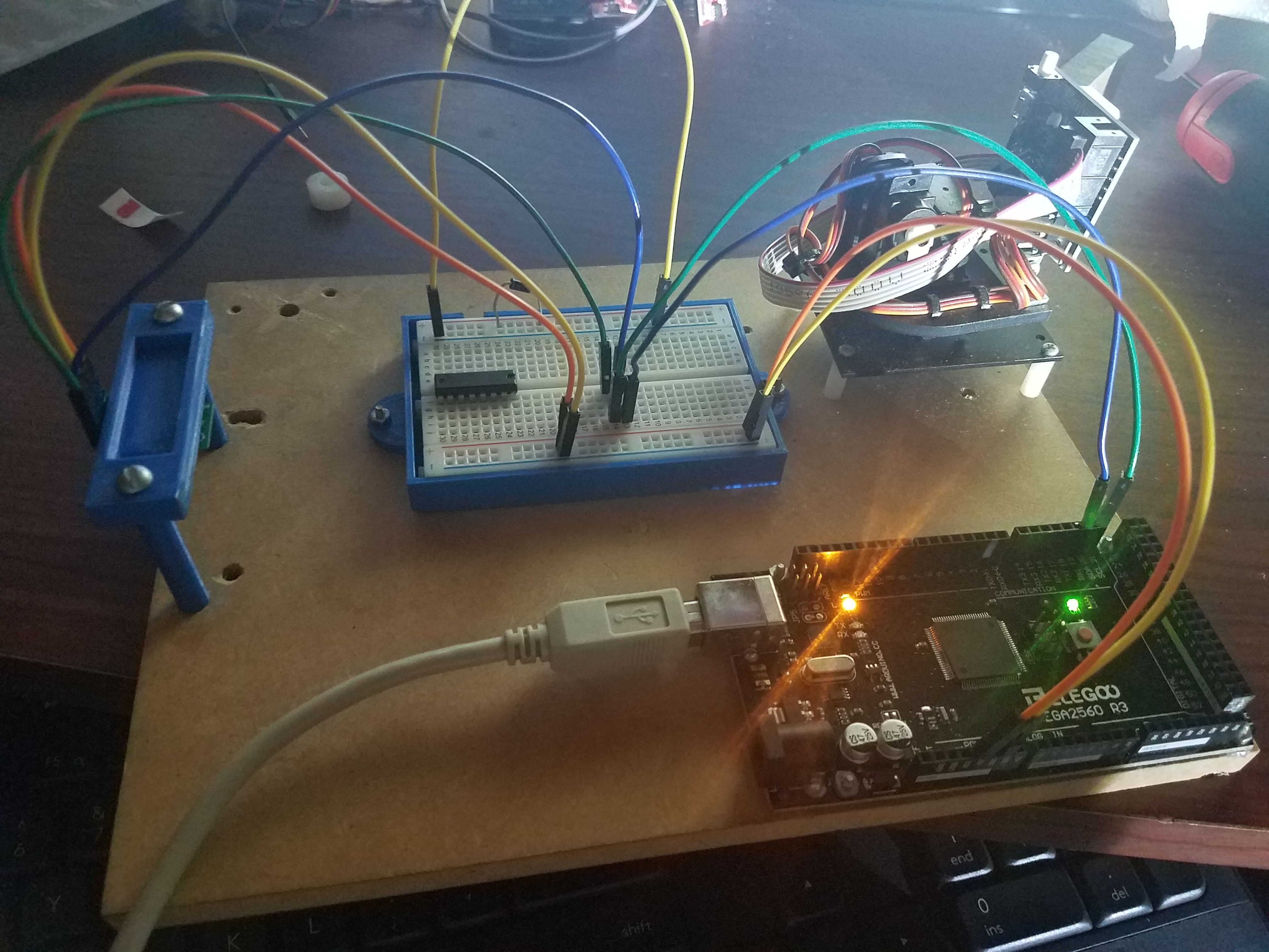
I have not fully implemented the MinIMU onto my system, I was testing it out first on an “ideal” scenario to test out the MinIMU and find out how it works. I have it mounted on a flat board, which can be seen in the first picture. I am powering the MinIMU with the 5V pin from an Elegoo Arduino Mega.The cables are color coordinated and are as followed
Color - Arduino - MinIMU
Orange - 5V - Vin
Yellow - Ground - Ground
Green - Port 21 (SCL) - SCL
Blue - Port 20 (SDA) - SDA
Picture 1: Current scenario of MinIMU with components facing down and attached to a PLA stand.
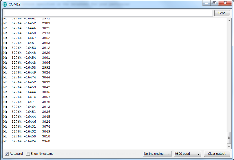
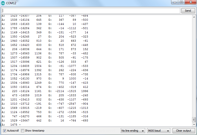
I am using the library Pololu has provided. I have ran the calibrate code unmodified, which were the results I posted yesterday. The second picture I have attached is the sample of the raw output from the Serial sketch.
Picture 2: Raw data output from MinIMU using the Serial sketch provided with the LIS3MDL library.
Please let me know if you need any additional information.
Thank you
-Cesar
Your test setup suggests several possible problems.
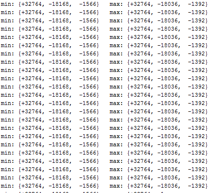
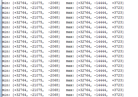
For tests the IMU should not mounted in a frame with metal parts. One channel of the magnetometer seems to be maxed out. One or both of the screws on the mounting frame may be magnetized and even if not will interfere with the local magnetic field.
Please remove the IMU from the mounting frame and post examples of the output (for both the magnetometer and the accelerometer) for several very different, hand held orientations.
The I2C bus is intended for short, on PC-board communications and often does not work as intended with long, loose wires such as shown in your photo. Try a basic setup with just the IMU connected directly to the Arduino board, using short leads.
I have connected the IMU directly to the arduino, however the shortest cables I have are about 8.25 inches long.
The current setup for the Arduino is it is directly connected to the IMU and is being manually held. There is nothing magnetic around the IMU and is about 2.5 feet away from my PC.
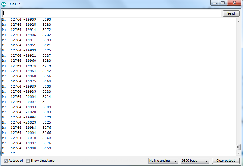
Here is the data from the magnetometer with the components facing down. The second orientation is with a rotation of about 90 degrees on the
Picture 1: Raw output for magnetometer with components facing down.
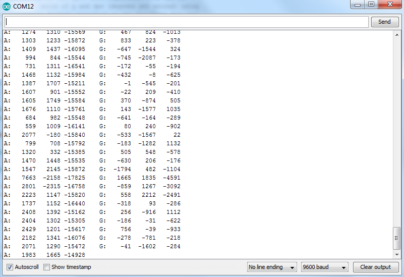
Picture 2: Raw output for accelerometer and gyroscope with components facing down.
Picture 3: Raw output for magnetometer with a 90 degree rotation about the x-axis.
Picture 4: Raw output for accelerometer and gyroscope with a 90 degree rotation about the x - axis.
Please let me know if you need any other information, additional information you need, or if there is anything I can do to fix it.
Do you think that I need to buy another one or is there anything I can do to fix it? I need to fix this issue soon to meet my deadlines. Thank you very much for the help you have offered so far!
Post the code that produced that output, using code tags.
Unless there are problems with the code, it does appear that the magnetometer is not working properly.
Hint: it is useful to print magnetometer and accelerometer readings on the same line. The accelerometer tells you which direction the sensor is facing.
Cesar, it is sounding like there could be an issue with the MinIMU since the x-axis seems to only output a maximal value. We test all of our boards before they ship, so the unit was likely working at some point. Do you recall if you ever inadvertently temporarily made connections to the board that were not appropriate? For example, connecting 5V from your microcontroller to the VDD (the 3.3V input ) pin, or reversing polarity by connecting 5V from your microcontroller to GND on the MinIMU and GND from the microcontroller to VIN on the MinIMU?
If you send us an email and reference this thread, I can look into helping you out towards a replacement.
In the meantime, if you want to try something as a workaround, you could try changing the magnetometer’s full scale setting. You can try adding the following line after mag.enableDefault();: :
mag.writeReg(LIS3MDL::CTRL_REG2, 0x20);
If that doesn’t work, you can also try values of 0x40 and 0x60. This might help you get usable readings from the magnetometer if the problem is that a magnetic distortion is causing the reading to max out at the default full scale.
-Jon
Jon, I am always cautious whenever I work with any sensors. I know that because of how sensitive some can be, I always double check and follow any instruction that it may have to properly wire them.
I have tried your suggestion of usingmag.writeReg(LIS3MDL::CTRL_REG2, 0x20);, however it does not seem to changed any of the outputs for the x-axis. I am going to give it one last test tomorrow using a different Arduino and in a different environment to see if anything changes. If not, I will make sure to send an email with the thread linked. Thank you for the help.
-Cesar
Jim, I was using the Serial code that comes with the MinIMU. I have made no modifications to that code and uploaded the code as is. Here is the code from Pololu.
#include <Wire.h>
#include <LSM6.h>

LSM6 imu;

char report[80];

void setup()
{
  Serial.begin(9600);
  Wire.begin();

  if (!imu.init())
  {
    Serial.println("Failed to detect and initialize IMU!");
    while (1);
  }
  imu.enableDefault();
}

void loop()
{
  imu.read();

  snprintf(report, sizeof(report), "A: %6d %6d %6d    G: %6d %6d %6d",
    imu.a.x, imu.a.y, imu.a.z,
    imu.g.x, imu.g.y, imu.g.z);
  Serial.println(report);

  delay(100);
}
#include <Wire.h>
#include <LIS3MDL.h>

LIS3MDL mag;

char report[80];

void setup()
{
  Serial.begin(9600);
  Wire.begin();

  if (!mag.init())
  {
    Serial.println("Failed to detect and initialize magnetometer!");
    while (1);
  }

  mag.enableDefault();
}

void loop()
{
  mag.read();

  snprintf(report, sizeof(report), "M: %6d %6d %6d",
    mag.m.x, mag.m.y, mag.m.z);
  Serial.println(report);

  delay(100);
}
I have experienced a semi-permanent output lockup in a Honeywell magnetometer of the HMC series, simply by placing it near a refrigerator magnet. Powering the sensor down did not fix it. However, I was able to reverse the lockup and fix the condition by executing a “reset” command documented in the device data sheet.
I do not know if the LIS3MDL is similarly susceptible to lockup by nearby magnetic fields, but it is a possible explanation for such aberrant behavior. The data sheet specifies an absolute maximum field strength of 1000 Gauss, which is about 10x stronger than a typical refrigerator magnet (the Earth’s field is roughly 0.5 Gauss near the surface).
The LIS3MDL does have a “self test” function (ST bit in CTRL-REG1), but the data sheet I have does not very clearly explain what that function does. You might try setting the bit and reading the magnetometer. My guess, from looking at Table 3, Section 2.1, is that if the device is working correctly, you should read between 1 and 3 Gauss on the X and Y axes, and between 0.1 and 1 for Z. Then reset the bit and test again.
I ran some tests on the LIS3MDL magnetometer built into the Balboa robot, and it appears that the self test bit just applies an approximately known magnetic field to the sensor elements.
Here is the test program:
#include <Wire.h>
#include <LIS3MDL.h>

LIS3MDL mag;

char report[80];

void setup()
{
  Serial.begin(9600);
  while(!Serial);

  Wire.begin();

  if (!mag.init())
  {
    Serial.println("Failed to detect and initialize magnetometer!");
    while (1);
  }

  mag.enableDefault();
  char c0 = mag.readReg(0x0F);  //should be 0x3D
  char c1 = mag.readReg(LIS3MDL::CTRL_REG1);  //default 0x70 on Balboa
  Serial.print("Who Am I: ");
  Serial.print(c0,HEX);
  Serial.print(" CTRL1: ");
  Serial.println(c1, HEX);
}

void loop()
{
  static int i=0;
  char c1;
  //set and reset self test on loop index
  if(i == 10) mag.writeReg(LIS3MDL::CTRL_REG1,0x71);
  if(i == 20) mag.writeReg(LIS3MDL::CTRL_REG1,0x70);
  while(i == 30); //hang
  delay(500);
  mag.read();
  c1 = mag.readReg(LIS3MDL::CTRL_REG1);
  Serial.print(i);
  Serial.print(" ");
  Serial.print(c1, HEX);
  snprintf(report, sizeof(report), " M: %6d %6d %6d",
    mag.m.x, mag.m.y, mag.m.z);
  Serial.println(report);
  i++;
}
Here is the resulting printout, showing a large jump in the components for loop index 10-19, then back to background. The actual values printed will depend on the orientation of the sensor.
Who Am I: 3D CTRL1: 70
0 70 M:   3389  -4083    359
1 70 M:   3389  -4059    401
2 70 M:   3390  -4083    335
3 70 M:   3384  -4077    349
4 70 M:   3433  -4072    339
5 70 M:   3404  -4058    387
6 70 M:   3363  -4126    389
7 70 M:   3385  -4067    414
8 70 M:   3388  -4069    419
9 70 M:   3428  -4063    382
10 71 M:  16206   8788  -1206
11 71 M:  16164   8807  -1163
12 71 M:  16218   8815  -1190
13 71 M:  16195   8818  -1178
14 71 M:  16183   8817  -1124
15 71 M:  16209   8806  -1170
16 71 M:  16186   8809  -1172
17 71 M:  16179   8779  -1208
18 71 M:  16208   8822  -1148
19 71 M:  16172   8842  -1186
20 70 M:   3385  -4046    359
21 70 M:   3420  -4103    398
22 70 M:   3410  -4090    349
23 70 M:   3409  -4072    359
24 70 M:   3404  -4091    363
25 70 M:   3384  -4112    324
26 70 M:   3413  -4109    398
27 70 M:   3388  -4074    361
28 70 M:   3404  -4093    340
29 70 M:   3425  -4069    366
Hello Jim,
I have tried the code you have provided, here are the results of them
Who Am I: 3D CTRL1: 70
0 70 M: -32768   1638    274
1 70 M: -32768   1561    321
2 70 M: -32768   1555    358
3 70 M: -32768   1562    331
4 70 M: -32768   1570    278
5 70 M: -32768   1549    310
6 70 M: -32768   1594    310
7 70 M: -32768   1586    303
8 70 M: -32768   1596    295
9 70 M: -32768   1602    303
10 71 M: -32768  13981  -1889
11 71 M: -32768  13967  -1865
12 71 M: -32768  14028  -1906
13 71 M: -32768  14020  -1903
14 71 M: -32768  13994  -1885
15 71 M: -32768  13996  -1824
16 71 M: -32768  14005  -1877
17 71 M: -32768  14024  -1886
18 71 M: -32768  13985  -1872
19 71 M: -32768  14081  -1847
20 70 M: -32768   1430    466
21 70 M: -32768   1315   3248
22 70 M: -32768    915    714
23 70 M: -32768   4375   1465
24 70 M: -32768   1559   1888
25 70 M: -32768   1377   3732
26 70 M: -32768   1934   3039
27 70 M: -32768   3023    262
28 70 M: -32768   1816    124
29 70 M: -32768    563   1445
This is with the components of the facing upwards and the X-axis perpendicular to me. Thank you very much for your help, I greatly appreciate it. It does not seem like the IMU is working though.