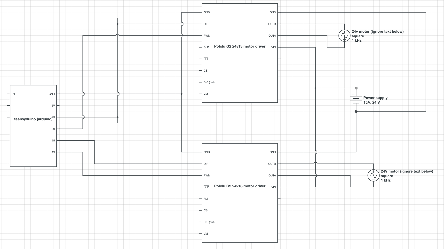
I used two g2 24v13 motor drivers Pololu G2 High-Power Motor Driver 24v13 connected to two 24V motors (use 0.55A at no load, 3.55 A at max load, and 15A stall current).
And when I started up the motor drivers, one of my 24v13 drivers seemed to have fried or short-circuited itself.
I believe the reason was that the power supply that I connected to the two drivers was a 24V 15A power supply, and so when I tried to start both motors at the same time, they would draw 30A in total which would be too much, and apparently that was too much for the pololu 24v13 motor driver board as well.
The fault flag is now active for the board which as the info sheet says means that the fault is due to over heating, under voltage, or a short circuit. It’s definitely not over heating since the temperature hasn’t increased on the board, and I don’t think it’s under voltage since I turned off everything and started it again and the motor driver does show 24V via my multimeter. So I think something inside the board has short circuited (everything external to the board is fine).
Is there any way to reset the fault flag now and have the board work again? (the board motor outputs are all 0 since it’s in the fault mode). I tried pulling the sleep pin low, but that only seems to temporarily disable the fault pin. When I set the sleep pin high again, the fault flag is active again and the board doesn’t move the motor.
Also is my only solution for next time I try the motors again to use two separate power supplies, one for each driver, or is there something else I can do with the motor drivers that will prevent them from breaking?
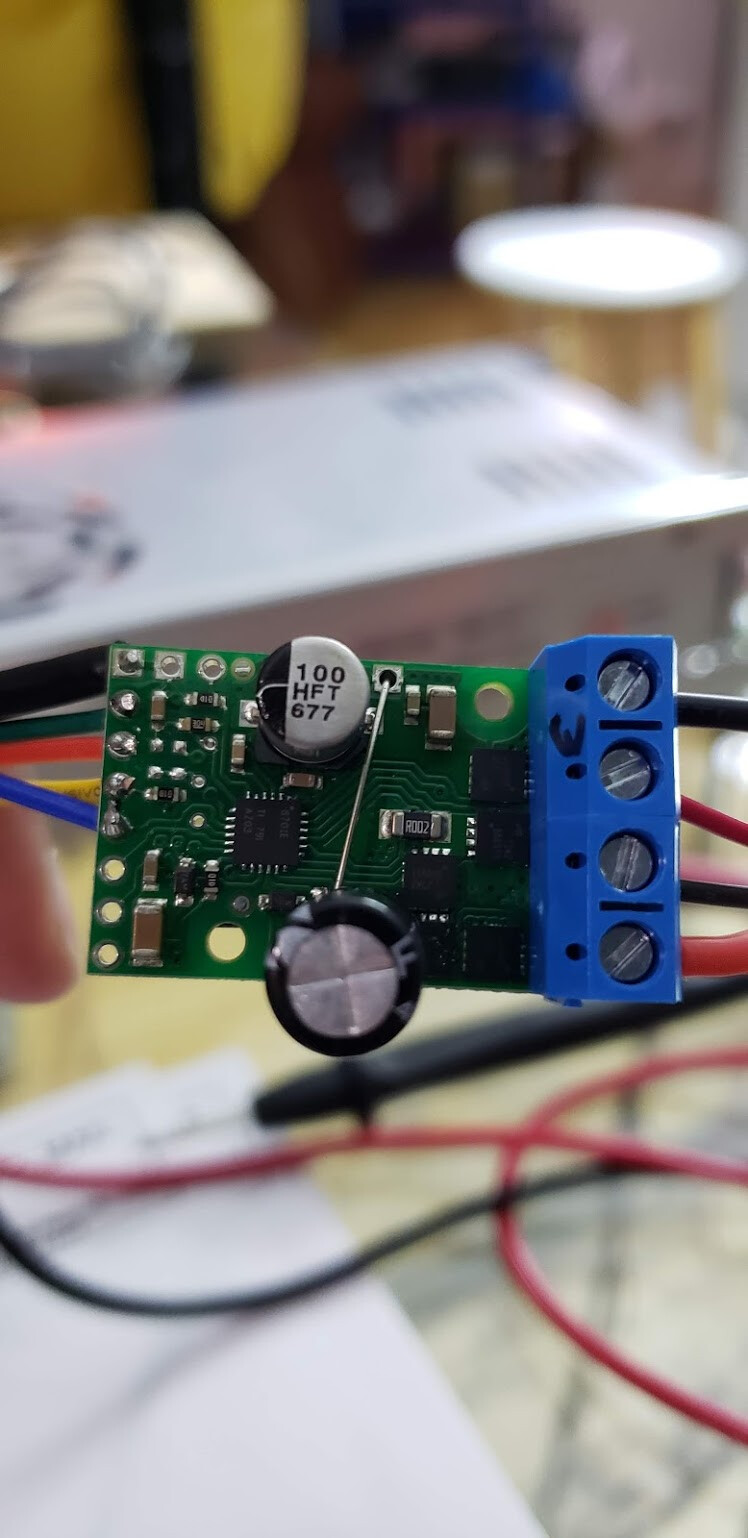
Unfortunately, if your driver is reporting a fault when there doesn’t seem to be any reason for one, it is likely damaged. Could you post pictures of the setup that show all connections as well as pictures of the non-working driver? Did the damage happen the moment you connected power? How are you controlling the drivers and are they set up to immediately go full speed when power is turned on?
Yes the damage happened immediately after I connected power and then started trying to turn the motors. I’m controlling the drivers from an arduino which interfaces with the two motor drivers which each connect with a motor.
When the power is turned on, I slowly accelerate the motors by increasing the pwm value by 25 every 500 ms (from 0 to 255 of the total pwm range).
Does the motor draw the full stall current even when accelerating slowly? Or would trying to accelerate even more slowly have helped here?
I have a follow-up question on the fuse locations.
I have a circuit where I used two g2 24v13 motor drivers Pololu G2 High-Power Motor Driver 24v13 each one connected to a 24V high torque motor (use 0.55A at no load, 3.55 A at max load, and 15A stall current).
And when I started up the motor drivers, one of my 24v13 drivers seemed to have fried or short-circuited itself.
I believe the reason was that the power supply that I connected to the two drivers was a 24V 15A power supply, and so when I tried to start both motors at the same time, they would draw 30A in total from the startup stall current which would be too much, and apparently that was too much for the pololu 24v13 motor driver board as well and it got fried in some way and won’t work anymore.
To prevent something like this from accidentally happening next time, where would you recommend adding fuses (or a relay?)?
Should I add one fuse each between the motor driver and motor? My concern with this is if the connection suddenly disconnects, will that harm the motor itself (I noticed that disconnecting the motor suddenly causes a big jerk in the motor as it halts immediately)? Or also with this method, would suddenly disconnecting them cause some kind of back current surge which would damage the motor driver, since there is a lot of current initially and then suddenly no current?
Hi, I had an issue where one of my motor drivers stopped working and I believe it was due to the current of the back EMF that was sent into the motor driver when I turned off the power supply while the motor was still spinning.
Here’s what my circuit looks like, it’s very simple just mcu → motor driver → motor.
I’m using the Pololu G2 24v13, and it says it has reverse voltage protection, but does that also mean it protects against reverse current protection as well or no?
If it doesn’t, how should I protect my motor driver from being damaged in the case of power loss again?
I’m using this motor driver Pololu High-Power Motor Driver 36v15
There is a !reset pin and the description on the site says “The RESET pin is pulled up to V+ through a 20 kΩ resistor. When held low, it puts the driver into a low-power sleep mode and clears any latched fault flags.”
It also says the default state is HIGH.
So should I be adding a resistor to this RESET pin myself and pull it up to V+, or does the description mean that the board itself is already pulling it up, and I don’t need to do anything?
I moved three of your other posts to this thread since they are all about the same damaged driver. Please keep all troubleshooting and discussions about this issue in this thread to make things easier to follow.
First, can you describe what was going on in your system when the driver was damaged? For example, how long after power was turned on did you notice something was wrong, and were both drivers connected and receiving the same signal from your Arduino? In some of your posts you said it was damaged when power was turned on, but in another post you said it was damaged when power was turned off. Did the damaged driver work correctly for you before?
Ramping up the speed of your motor slowly does help a lot with limiting in-rush current spikes. The best rate of acceleration for a system is dependent on many factors and is something that would need to be determined through testing, but the acceleration you implemented seems reasonable.
As mentioned in this thread you originally posted in, the best location for a fuse depends on what you want to protect and from what. Putting a fuse between the motor and driver would prevent the motor from drawing more current than the driver can handle, but if that is a concern, I recommend using the driver’s current limiting feature.
“I’m using the Pololu G2 24v13, and it says it has reverse voltage protection, but does that also mean it protects against reverse current protection as well or no?”
The reverse voltage protection the driver’s specifications refer to is protection against connecting power to the board backwards (connecting ground to VIN and power to GND). The driver also has built-in flyback diodes that help to dissipate excess energy cycling through the motor when the driver outputs are turned off. I do not expect your case to require extra protections and if the driver was damaged on power-up, I do not expect back EMF was at fault.
“So should I be adding a resistor to this RESET pin myself and pull it up to V+, or does the description mean that the board itself is already pulling it up, and I don’t need to do anything?”
You do not need to do anything with the RESET pin.
Immediately after I turned on the power, I saw that one motor was spinning but the other was not. That was immediately suspicious since both drivers were receiving the same signal from the arduino. So I then turned the power off to be safe and tried each motor driver individually and one of them did not work anymore, so it seemed like something wrong had happened.
Like I said before, I first tested the system with one motor and driver at a time to make sure they individually worked. I then used both drivers at the same time and connected one driver to my high torque 24v motor (GR-WM4 24V DC High Torque Low Noise 35rpm Worm Gear Motor - Gimson Robotics | The linear actuator and electric motor specialist) and connected the other driver to a small 24v .095A fan motor, and both drivers and motors worked fine here. It was only then that I connected both drivers to my high torque motors that one of the drivers failed.
So I’m not entirely sure in which direction this may have happened. I was hoping you might have some insight into this.
It may have been that it was damaged when I turned power on. But I had a theory that it could have been when power was turned off because the motor would still have been trying to turn when I unplugged power, so the back emf would have been sent back into the motor driver. And thus I thought the back emf could have caused the issue on power off.
Ah ok, this is really great to know.
But could putting the fuse between driver and motor cause any issues to the motor or driver? I noticed during testing with one motor at a time that if I immediately turned off the arduino power, then the motor would have a big backward jerk since it lost its input voltage. Not sure if that is bad for the motor.
Likewise, could breaking the connection between motor and driver somehow harm the driver itself? Perhaps due to a big change in the current/voltage from one step to the next and the logic on the driver board not expecting such sudden changes in the outputs?
I moved one of your other posts to this thread. Please keep all of your questions about the 24v13 high-power motor driver in one of your two existing threads even if they do not seem directly related to our troubleshooting.
Cutting off power to an inductive load (like a motor) quickly can cause a voltage spike at the motor terminals. This could is generally not an issue for the motor and I don’t expect the jerk you saw when is was disconnected damaged in. That kind of spike could damage connected electronics if they are not protected, but as I mentioned in my last post, the driver’s integrated flyback diode should protect it in most cases. This situation also applies if the disconnection happens because of a fuse.
It is hard to say for sure at this point whether the damage happened when you powered off the driver or when you powered it back on and noticed the motor didn’t spin. Was the driver that broke the one that had already been tested with your high torque motors? Could you post a datasheet or link to specifications for the motors? Could you post pictures that show the full setup with all connections?
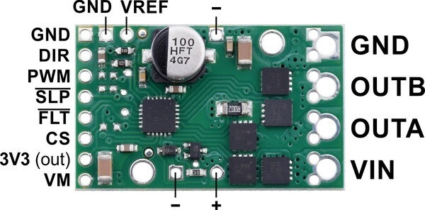
All of the ground pins on the high-power motor driver boards are directly connected to each other.
Thanks for the pictures;I don’t see anything obviously suspect in them. I didn’t realize you were using one G2 24v13 and one G1 36v15, but it seems like you probably swapped the 36v15 in to replace the damaged driver.
I suspect the driver was damaged by a voltage spike on its power input. Since you were accelerating the motors slowly on start-up, it seems pretty unlikely to me that that is when the driver was damaged. It is more likely an input voltage spike would happen if the motor was stopped too fast. Stopping suddenly leaves current circulating in the motor that has to be dissipated. The fly-back diodes on motor drivers let that current flow back to the power supply, which is generally fine for batteries, but can be problematic for bench-top supplies like yours. They block that back flow of current causing a voltage spike. If that is what happened, adding additional capacitance or a TVS diode across VIN and GND on the driver could help. The best thing to do though is look at the VIN node with an oscilloscope while carefully running the motors to see what is really going on.