hi sorry for the english but i’m young italian, i’m working on it.
I have a problem whit the QTR library ,maybe , i’m working with Arduino UNO and i have TWO QTR-1rc , i 'm buliding a line-follower but , the code give me always -1000 on the serial monitor and it doesn’t see the black-white change
this is the code thanks for the help
#include <QTRSensors.h>

QTRSensorsRC qtr((unsigned char[]){12,13},2);

void setup ()
{
  Serial.begin(9600);
  int i;
  for (i = 0; i < 250; i++)
  {
    qtr.calibrate();
    delay(20);
  }


}
void loop()
{

  unsigned int sensors[2];
  // get calibrated sensor values returned in the sensors array, along with the line position
  // position will range from 0 to 2000, with 1000 corresponding to the line over the middle sensor
  int position = qtr.readLine(sensors);

  int error = position - 1000;

  if (error < -500)  // the line is on the left
  {Serial.print (error);
  }

  if (error > 500)
   {Serial.print (error);} // the line is on the right
}
Can you just start by printing out raw, uncalibrated readings from your sensors and see if those make sense? If those look good, then try running the calibration routine and printing out the calibrated readings and see if those look reasonable.
ok , and how the calibration works ?
i tried this , but it does’nt work
#include <QTRSensors.h>

// create an object for your type of sensor (RC or Analog)
// in this example we have three sensors on analog inputs 0 - 2, a.k.a. digital pins 14 - 16
QTRSensorsRC qtr((char[]) {2, 3}, 2);
// QTRSensorsA qtr((char[]) {0, 1, 2}, 3);

void setup()
{
  // optional: wait for some input from the user, such as  a button press

  // then start calibration phase and move the sensors over both
  // reflectance extremes they will encounter in your application:
  int i;
  for (i = 0; i < 250; i++)  // make the calibration take about 5 seconds
  {
    qtr.calibrate();
    delay(20);
  }

  // optional: signal that the calibration phase is now over and wait for further
  // input from the user, such as a button press
}
That code will calibrate the sensor when it is in a certain setup, but I do not know if that is the right code for your particular setup. Could you tell me more specifically what you are trying to do with the sensor? How do you have your sensor connected to the Arduino? What process are you following when you try to calibrate the sensor?
Hey, we are working with pololu sensors(QTR 8rc) sensors for the first time to make a line follower robot.
We uploaded the QTRRCExample code from the library for calibration.
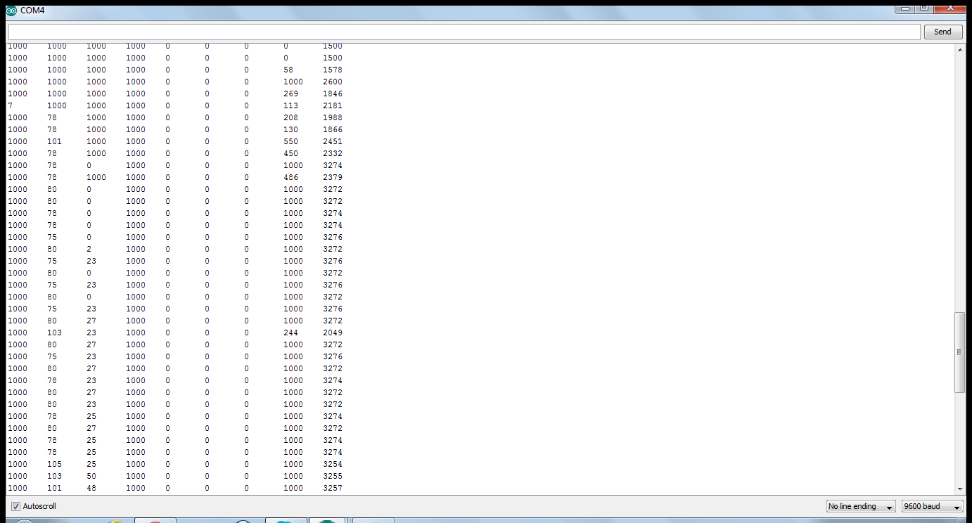
Can you help,by telling us what we can infer from the values(screen shot of serial monitor and connections enclosed) and how to use them in our line follower code?
Thanks
1000 signifies that you are measuring something that is as dark as or darker than the lowest reflectance reading encountered when calibrating, and 0 signifies that you are measuring something that is as light as or lighter than the highest reflectance reading encountered when calibrating. The first eight columns are sensor readings, and the ninth column is the result of an algorithm meant to tell you where the line is, but I think that column is not going to be meaningful given your current sensor readings.
For line-following, you should keep track of the where the line is and the algorithm should try to maneuver the robot so it tries to center the line on the sensor array. You can find line-following examples for the QTR sensor here.
Hey Jeremy,
Thanks ,that was informative.I saw a few codes online which use the value(750) to indicate a logic high.As in,if the value of the sensor reading is over 750, it is over a black line.So,can i interpret my readings a similar way? From our calibrated readings,can we take a similar value?? And can the emitter pin be off for QTR 8RC sensors?
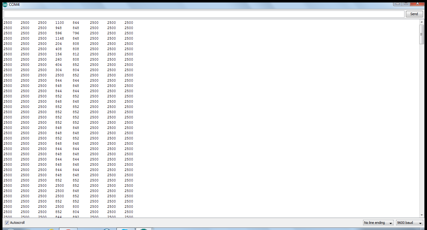
Here are the readings when the QTRRCRawValuesExample code was run, with the sensors over a white surface alone.
Aren’t the readings supposed to read 0 in all columns over a white surface?
Please help
It looks like the sensor is not reading properly. How do you have the sensor connected to the Arduino? Is there anything else connected to the Arduino? Could you post pictures and a diagram of your setup? Also, what changed in your setup between now and your previous readings?
It is possible that the IR LEDs are not functioning as expected. A cell phone camera can usually pick up infrared light. Could you try using your cell phone to see if all the LEDs are lighting up? More information on this can be found here. Separately, you can test to see if the IR detectors are working by holding them up to a good IR light source like a sunny window to see if the values change.