Hi !
I bought 3 Pololu USB AVR Programmers and can’t seem to get them working.
I have a custom board with an old AT90S8535 on, I can program the board with my STK500 using the 6pin ISP header, no problem. But when I connect it to any of the three Pololu USB AVR Programmers it fails during “Entering Programming mode” in AVR Studio 4.0.
I have also tried with avrdude, it gives me :
avrdude: stk500v2_command(): command failed
avrdude: initialization failed, rc=-1
Double check connections and try again, or use -F to override
this check.
avrdude done. Thank you.
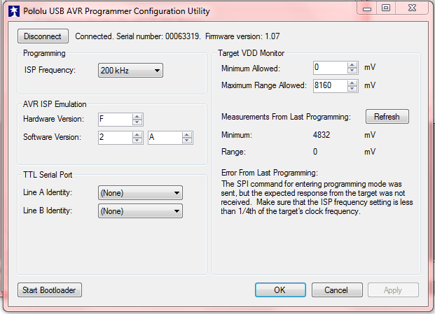
I have attached a picture of the Pololu USB AVR Configuration util with shows fault with SPI command.
I have checked the voltage settings, and tried many combinations.
I have gotten it to program one or two times out of 100, so I’m not shure what is wrong. STK 500 never failes at all.
BR,
Ole A.
Hello, Ole.
I am sorry you are having trouble with the Pololu USB AVR Programmer. We have not tested the programmer with the AT90S8535 and I do not know of any customers who have done that either, so there might be trouble getting it to work. Could you please post the full AVRDUDE command you are running? Are there any components between the target chip and the programmer, or are the programmer’s pins directly connected to the chip?
–David
Hi David !
Thank you for your fast reply !
The complete avrdude command is :
avrdude -p 8535 -c stk500v2 -Pcom2
I have not tested any other controllers, as I have a stock of about 2000 8535s 
The programmer is connected directly to the chip, nothing between.
Ole A.
I am reading the AT90S8535 datasheet and trying to determine what might be going wrong. The “Serial Downloading” section of the datasheet documents what we are trying to do. In that section, it says:
What kind of clock or crystal is the AT90S8535 connected to? The frequency matters too, so what frequency is the clock or crystal?
–David
Hi !
I’m running a 4Mhz Crystal as main clock connected directly to the XTAL pins with 12pF load.
Ole A.
Hi again !
I tried changing the crystal to 8MHz, and it did not help, could it be that the delay before the AVR responds is too short for the old controllers ?
I tested a board I found with an mega128L, and it worked perfectly.
BR, Ole A.
Hi !
I tested even more today, and I’ve got an acient at90S2313 working fine,
this controller is older than the 8535, so my issue seems to be related specificly to the 8535 part.
I looked at the two datasheets wide by side and the only difference I can see in the text and the drawing is that on the 8535 the RESET pin is shown to be connected to GND ! It might just be a fluke, I don’t know.
BR, Ole A.
Unfortunately, I do not know what might be going wrong. I would buy my own AT90S8535 and try to debug this with you, but it seems like it is pretty hard to buy the AT90S8535 online, and according to Atmel, that chip is a mature product and not recommended for new designs. If you want to look at the programming lines on an oscilloscope and diagnose the problem, that might allow me to make a firmware update that fixes the problem, but you should probably just use the programmer you have that works.
–David

