Here is device manager after the programmer is plugged in
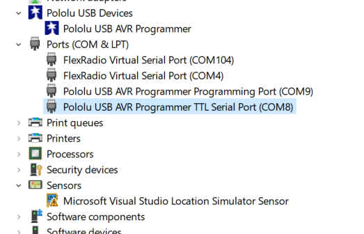
Here is device manager after the programmer is plugged in
I have the programmer hooked up to a win 10 notebook and the six pin programming cable wired to a board that is known good but I have built it with only the required ICP components and power supply. Power supply is 4.91 volts at the chip . Reset pin is pulled up with 10 k resistor and the 6 pin ICP connector is wired per Atmel instructions
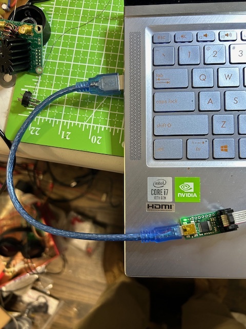
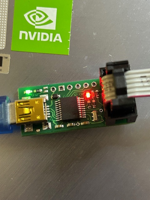
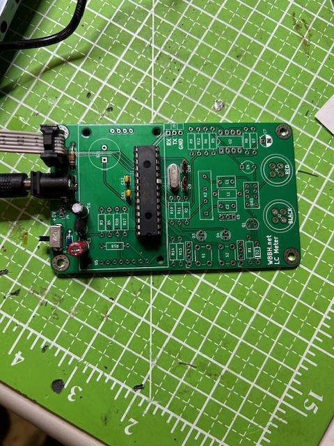
I have included a photo of the programmer and board . The green led is on and the red led is flashing
I will include a screenshot of device manager and all seems to be working.
When I plug in the programmer the red led stops blinking and is on steady
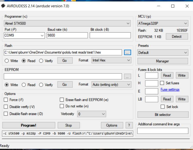
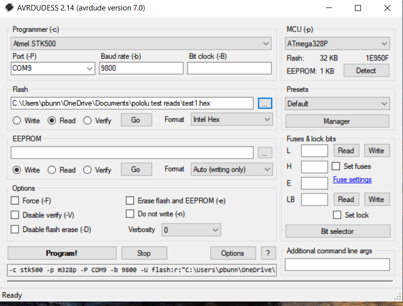
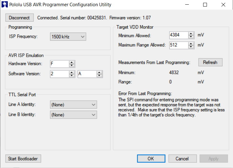
I power up the board with the 328p and use AVDudette so I can show the settings and have included a screen shot
I try to read the fuses and get digital activity on the green led but no read data
I try to read the chip flash in hex and get a bit longer activity - maybe a second but nothing is stored in the file designated as the read file.
I am probably doing something wrong
Pat
Here is AVDudette to show a graphic image of AVDUDE
Here is AVDudette showing my setup to read the flash in the chip. When I try to run it I get nothing in the designated file.
Here are photos of my setup. The first is the cable from the notebook to the programmer.
The second is a close up of the programmer.
The last is a view of the board that has the Atmel 328P. The chip may not have a bootloader. I am not sure.
Hello.
Why do you say the board is “known good”? Have you programmed it recently in some other way? Does the AVR show any sign of life, and do you know what was programmed onto it?
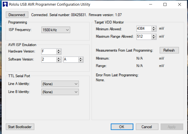
As Brandon mentioned, the Pololu USB AVR Programmer Configuration Utility can give you a more detailed error message when something goes wrong. After attempting to program your board, please start the Pololu USB AVR Programmer Configuration Utility (which you can find in your Start menu), take a screenshot of it, and post it here.
You did not mention the programmer’s yellow LED. If it is off, it means the programmer is not detecting the power supply of your device. If that is the case, the configuration utility should verify it.
–David
The yellow led is flashing when the board to be programmed is connected and powered on. When the power switch on the board to be programmed is turned off, the red led begins to flash.
The board to be programmed has been programmed before. I can’t say for sure the state of the 328p that is currently plugged in as it has been through many itterations of trial programmings. I have a few brand new 328ps that I really don’t want to screw up until I am reasonable sure things are ok. I have several Ardunio working boards that I can hook up and attempt to read.
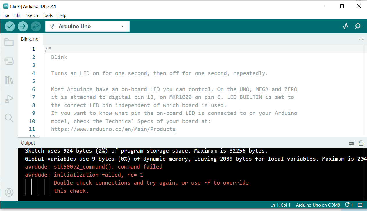
I tried to connect the programmer to Atmel studio 6.2 but it could not find the programmer.
I then loaded IDE and then loaded the blink program.
It compiled fine, so I connected the programmer to IDE and attempted to load the program to the board with the upload sketch with programmer. Some activity was noted on the green led and the programmer ended up with a red led, the green led and a flashing yellow led.
I recommend changing the ISP frequency to 200 kHz in the utility. Make sure to click “OK” or “Apply” after changing it. As the error message indicates, the ISP frequency needs to be less than 1/4th of the target’s clock frequency, and maybe your AVR is running at 1 MHz. Note however that if you use the -B option when running AVRDUDE, that changes the ISP frequency.
If that does not work, I recommend using a multimeter to check the continuity of all 6 connections. The programmer is correctly detecting the power voltage of your board, but maybe one of the data lines is not connected properly. With the system powered off and disconnected from USB, I would touch one end of the multimeter directly to an ISP pin on the bottom of the programmer, and touch another end directly to the corresponding pin on the ATmega328P to make sure there is continuity (a resistance of a few Ohms or less). It would also be good to check for continuity between all possible pairs of ISP pins as well, to see if there is something shorting two of them together.
–David
I have confirmed that all of the pins on the connector go to the proper pins with a lab grade meter. All connection were less than 0.3 ohms
The board that I am trying to program is running at 16 MHz ( crystal controlled)
Lowering the programming speed did not help.
Pat Bunn
The default clock of the ATmega328P is 1 MHz, (derived from the internal RC oscillator), so it is good to use 200 kHz for the ISP frequency whenever you are troubleshooting.
When your Pololu USB AVR Programmer v2.1 arrives, I recommend using it to read some of your Arduino boards so you are sure it works, and then seeing if you can read or program the LC meter board with it.
–David