Hi,
I am using Pololu QTR-8RC reflectance sensor array with Intel Edison and Arduino board to make a line following automatic car.
I’ve downloaded the Arduino libraries from Github, and sketched the given example “QTRRCRawValuesExample” to my Arduino board, but it seems that the sensor do not respond. I am wondering if there is anything wrong with my sensor or I do not take the right steps.
Here is my board and screen shot of serial monitor:
Can anyone help me solve the problem? I’m in a hurry  Thanks a lot!
Hi everyone,
I am not sure whether the last question is posted successfully, so I hope to repost the question.
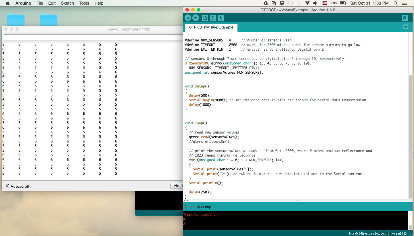
I tried to sketch the example – QTRRCRawValuesExample from Arduino Libraries to my Arduino board, however, there are only values 5 showing on serial monitor, which means the maximum reflectance. I put the white/black paper 3-9mm above the sensor.
Can anyone help me with this problem? Is there anything that I haven’t paid attention to?? 
Hello.
Are you only using the Arduino and QTR-8RC sensor array in your tests, or are you using the Edison somehow too? If you have the Edison currently in your system, can you isolate the Arduino and QTR-8RC sensor to see if the problem persists?
Do you have the Arduino pins connected as described in the code’s comments (e.g. LEDON to pin 2 and sensor outputs 1 through 8 connected to pins 3-10 )?
If double checking of those things did not help, can you post a video, or some pictures, that show all of your connections and how you are testing the sensors?
By the way, forum posts from new members have to be approved by moderators before they will become visible. We combined your posts into one thread since they were about the same topic and had slightly different information, and you should be able to post freely now.
-Brandon
Hi Brandon,
Thank you very much!
This is the connection of my Edison board and QTR-8RC sensor array.
I have doubled checked that the pins are connected right. The 1-8 pins of the sensor are connected to 3-10 on Edison.
I am wondering if the problem is that the board I use is different with Arduino board? And should I modify the code given in the example?
The board is Intel Edison with kit for Arduino, the breakout board is compatible with Arduino Uno(only 4PWM is 6PWM instead).
I am not that familiar with the Edison and Arduino Breakout Kit, but it is very possible that there is some difference with that board that makes our library not work with it. Do you have an Arduino Uno you could try your setup with to make sure everything else is working correctly?
-Brandon