Hello all,
Today i have wired up my new Pololu G2 High-Power Motor Driver 18v17 for a quick test, but the motor driver is not working as expected, it is not moving the motor at all.
Also, is it okay to use arduinos analogWrite(11, 200) for example? or do i need to use something else for the pwm signal?
My Specs are as followed:
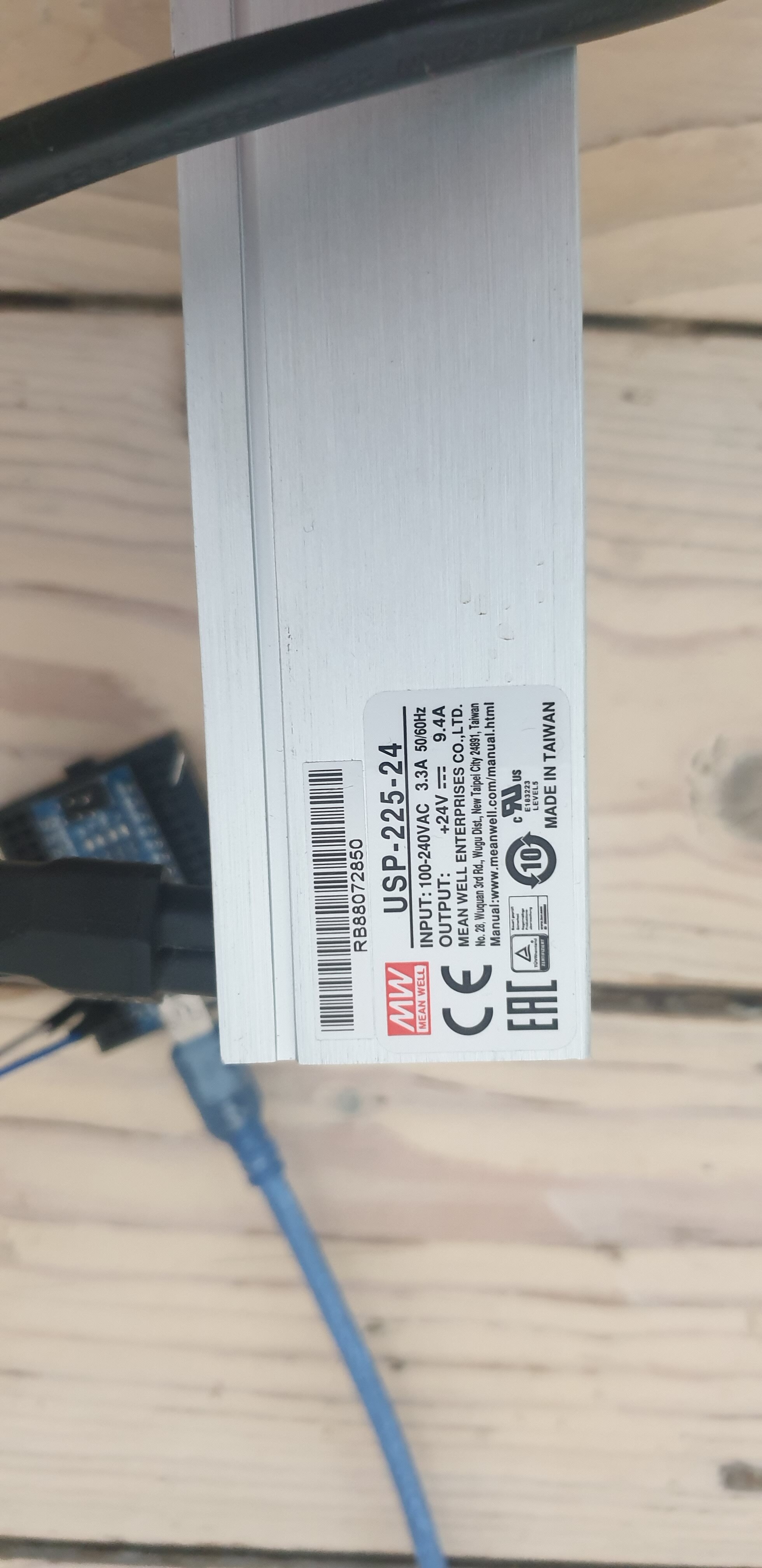
Power Supply: 24v 9.4A VDC (USP-225-24)
MicroController: Arduino NANO (PIN 10 IS DIR) (PIN 11 IS PWM)
Motor: Model: XD-3420 (Voltage(Optional): DC12V/24V)
Things i checked and tried:
- Motor works when connected direct to power supply.
- Power supply is outputting 24V as described, drivers max voltage is 30v, so no problem there.
- Microcontroller is outputting a pwm signal on pin 11, and pin 10 is set high for the direction.
- Soldier connections are all fine.
Any help would be appreciated, but i think it could be a faulty driver board, all the specs seem to be in range so, if anybody has got ideas, i would be happy to hear it, thank you in advance.
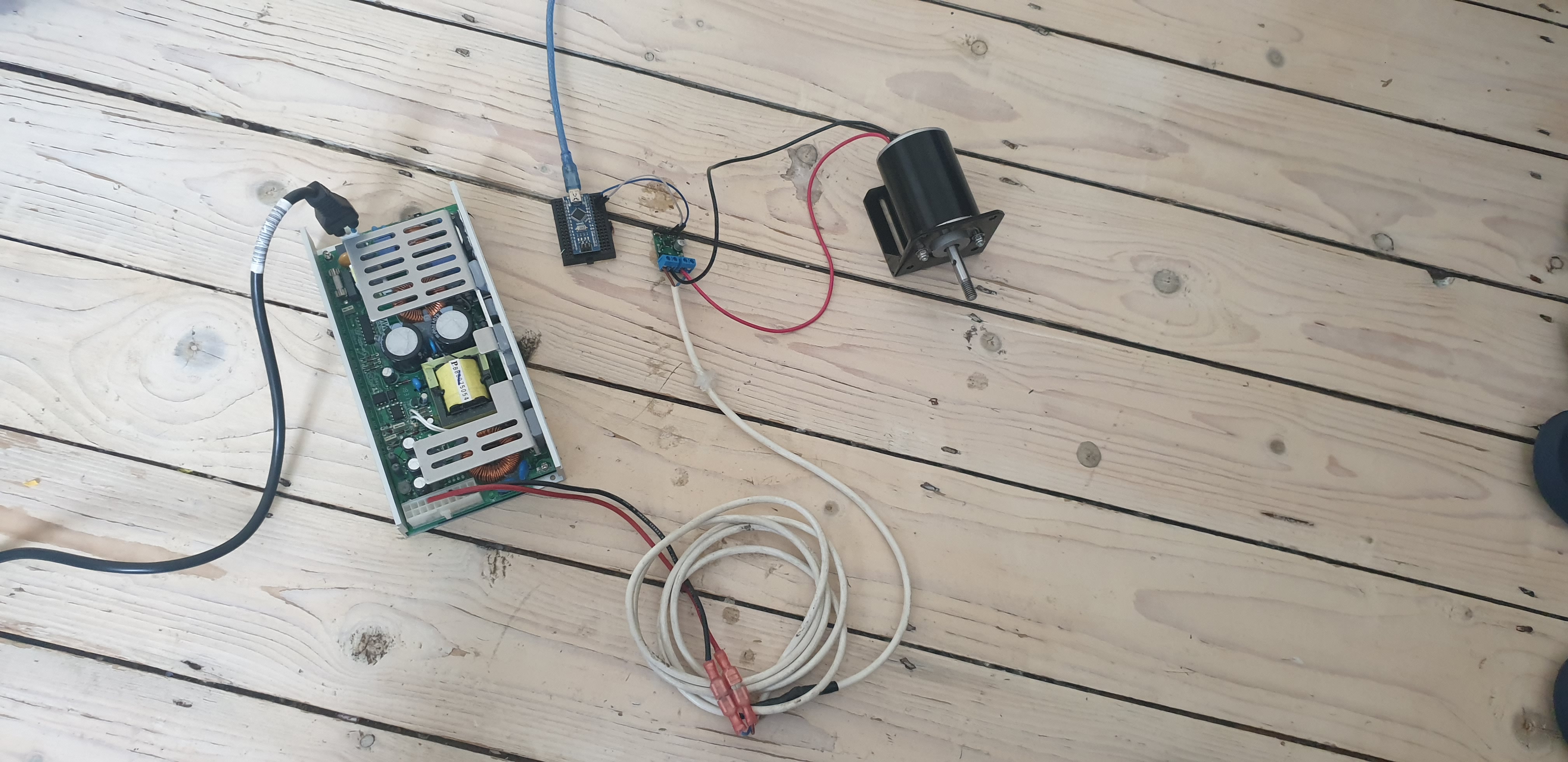
setup images attached:
Hello.
It looks like you do not have ground connected between your Arduino and the driver.
Also, I do not see any additional capacitance added to the driver. As we say on the product page, we generally recommend adding at least a few hundred uF, and it should be even higher if your power supply is more than about a foot away (your power supply connection looks to be through many feet of cable).
-Patrick
Thanks for your reply, I have 1k uf capacitors ordered and should be with me this week, ill give it a go, also what do you think about the pwm signal? Is the arduino able to supply a pwm signal via analogwrite function or do i need to ise something else?
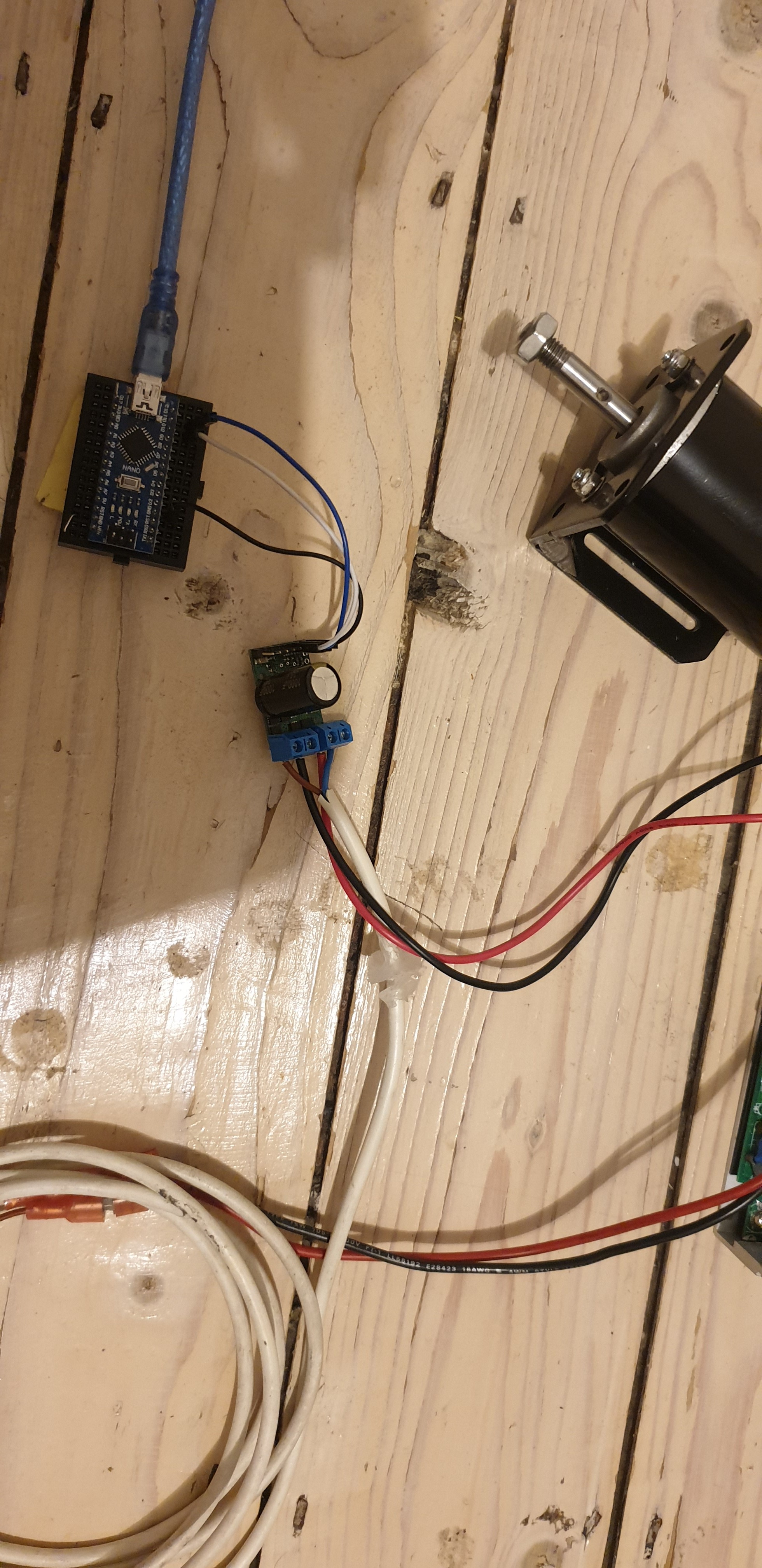
**Update
I have recieved my capacitors today, so i soldered one on and connected ground to the arduino, but still no effect, the motor should be moving atleast some direction, i cant see why not, how can i check if the driver board is working correctly? thanks, images of new setup attached.
In your first post, you said that you were wiring Pin 10 to DIR and Pin 11 to PWM, but your picture seems to show the opposite, which could explain why your program is not functioning as expected. The analogWrite function will provide a suitable PWM signal to the driver as long as you are using a pin that is capable of PWM. You can see which pins are PWM pins on various Arduinos here.
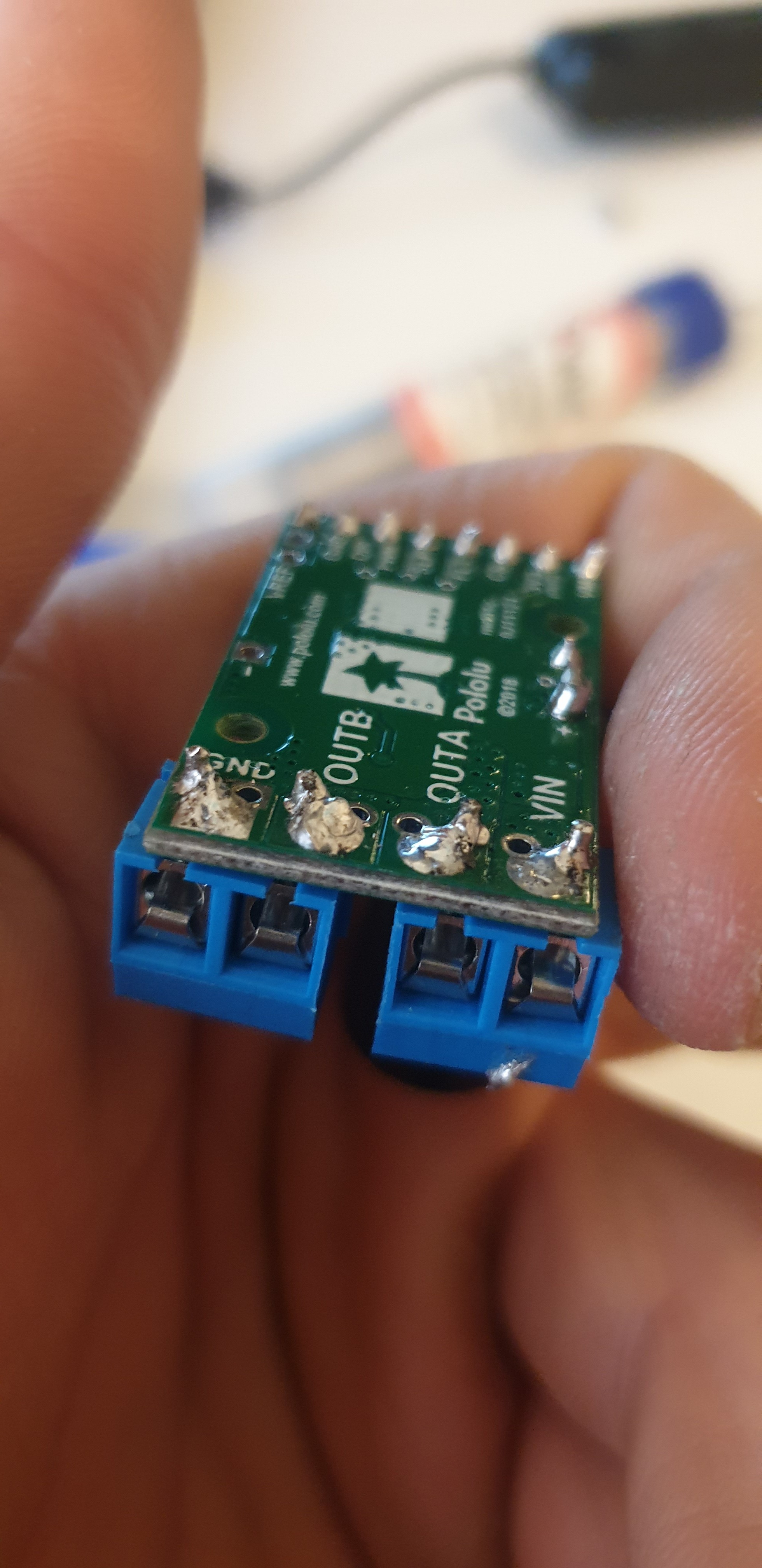
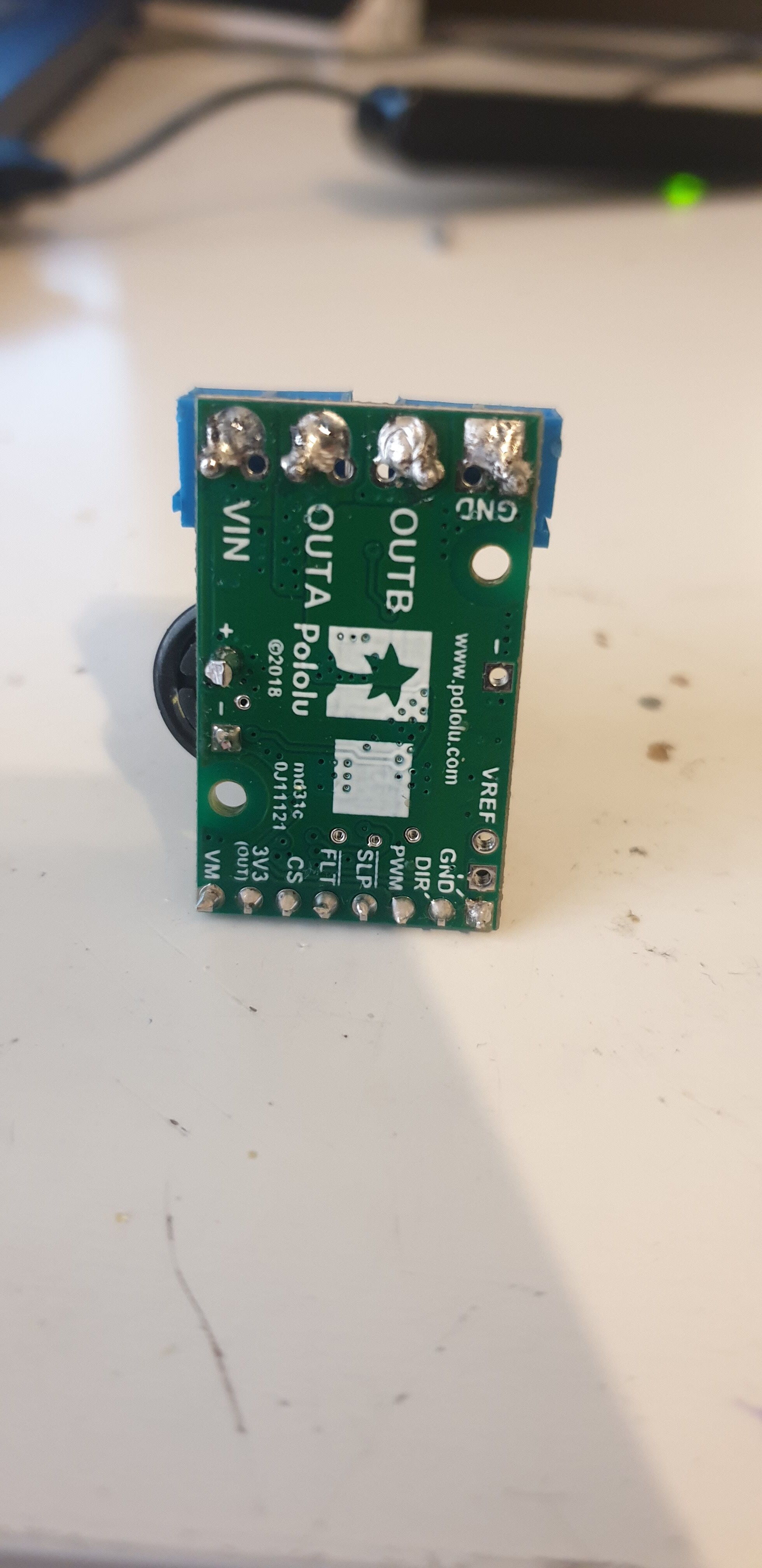
Can you disconnect the motor from the driver and instead use an oscilloscope to look at what is going on? Please post some screenshots of that along with some close-up pictures of your soldering.
By the way, you might find this video about installing terminal blocks helpful. It might be difficult to uninstall your terminal blocks on this driver (and it probably is not worth trying), but this could be a useful reference for soldering terminal blocks onto boards in the future.
-Patrick
Hello, sorry i mixxed pin 10 with 11 in my first post, i can confirm that they are 100% wired correctly, also i do not have an oscilloscope. i have tried everything i can, running out of options here, i can send you an image of my soldier later on, but im sure there isisnt any problem there, is there anything else i can try? is there any way to identify if the driver is malfunctioning or deffective? thanks for the help 
We test every unit we make, so your driver was probably working at some point. However, it is possible that it has been damaged. Can you try disconnecting the motor and testing the driver in a steady-state configuration (i.e. drive the PWM pin high)? Then, can you use a multimeter to measure voltages at various nodes (signal inputs, power inputs, motor outputs) and the current draw of the driver.
By the way, you can get a decent scope these days for a few hundred dollars, so we strongly recommend you invest in one. It will save you a lot of time and give you better understanding of your systems, which enables better designs, better margins of operation, etc. Without one, you’re left mostly just guessing about what might be happening, which is not a great way to operate.
-Patrick
Okay i will give that a go tommorow evening and will update you, thanks.
Hello, i have tested the driver with a voltmeter today, i drove the PWM signal high as you have suggested, and even re-solidered connections just incase, but still nothing…
Results:
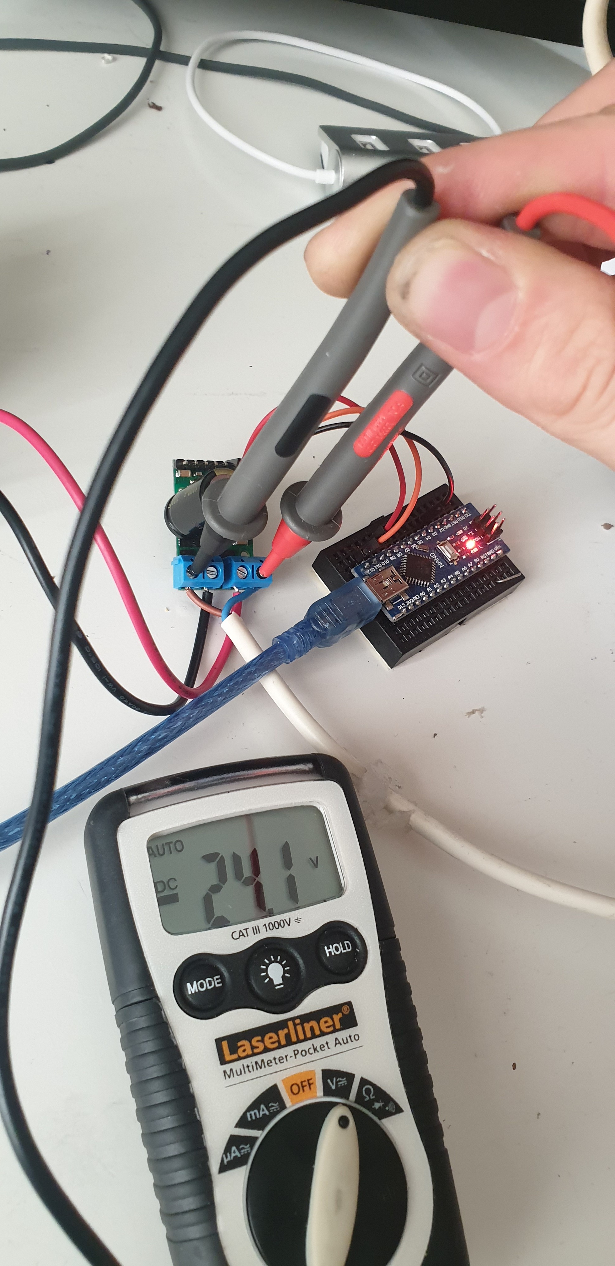
Voltage In: 24.1v
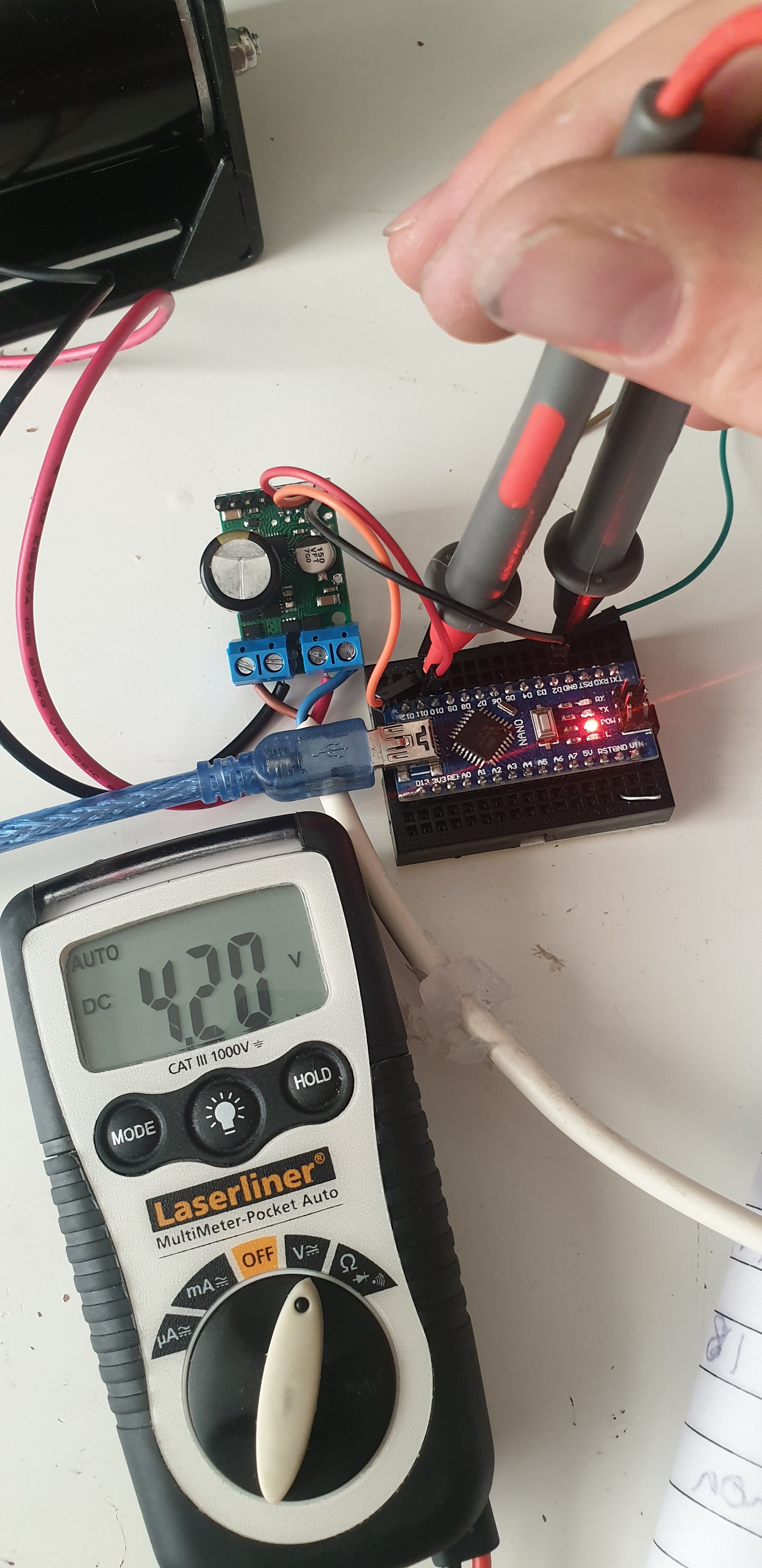
PWM Signal: 4.20v
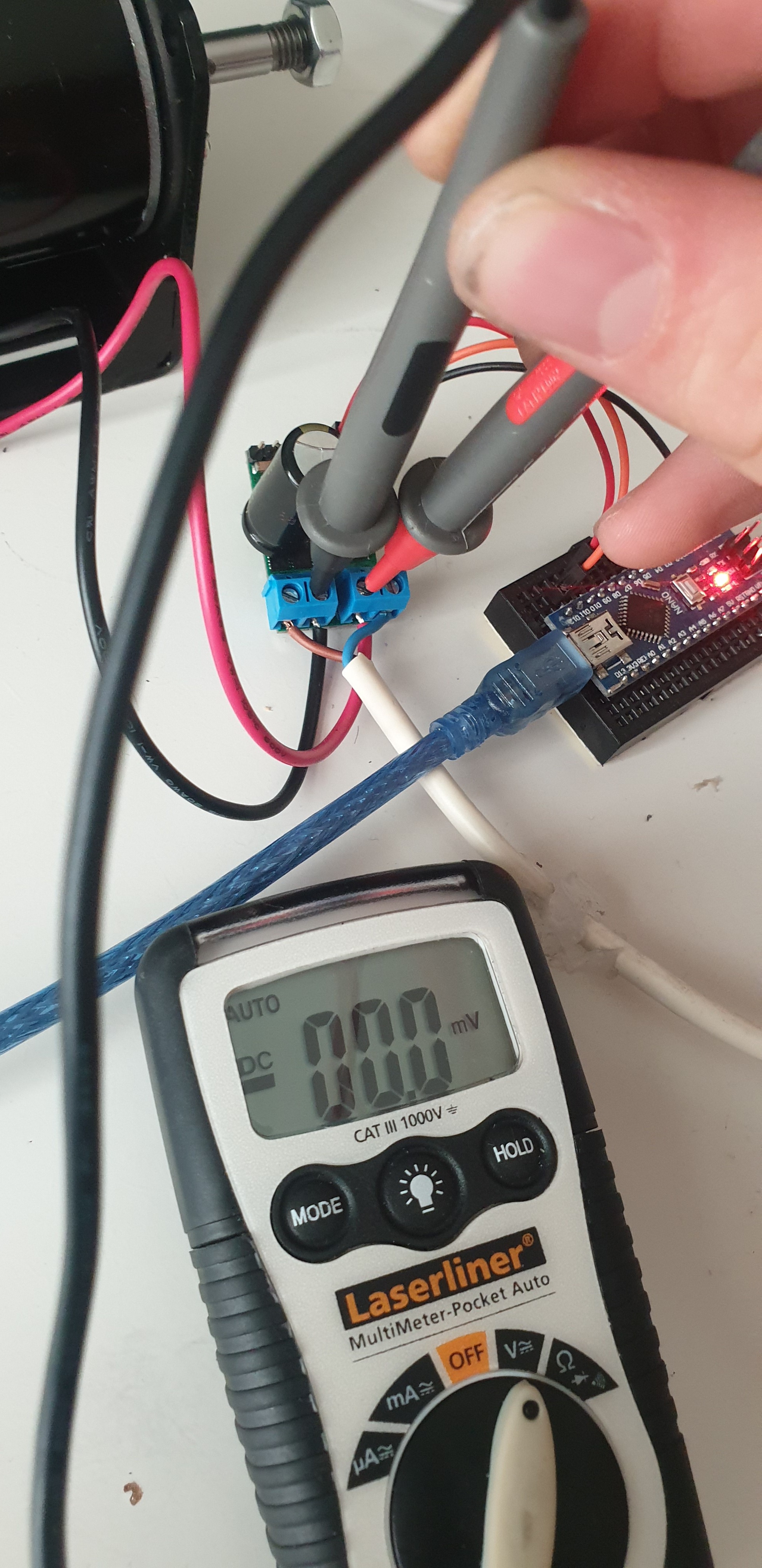
Motor Output: 0.0v
I am running out of options here, please help…
Thank you for the pictures. Unfortunately, it is starting to seem more certain that your driver is damaged. Unfortunately, it is easy to damage electronics like this in a variety of ways, including accidentally applying stray voltages or even something as simple as electrostatic discharge (ESD). Additionally, the way you had it connected before with no ground could also have damaged it.
We can help you out with a replacement if you would like to try again, and I have sent you an email with more information.
-Patrick