motor driver is connected to both raspberry pi. and 18650 batteries. a light blue light shines on the motor driver board. i used the oscillations to test the voltages for M1A, M1B both says negative zero. any idea how to fix that?
libraries are installed correctly. im using python 3 to run
Hello.
If you have not already, can you try the unmodified example program from our Python library with no load attached to the driver outputs and let me know if you see any of the green or red motor indicator LEDs turn on? Can you also post some pictures of your setup including ones that show all of your header and terminal block solder joints?
- Patrick
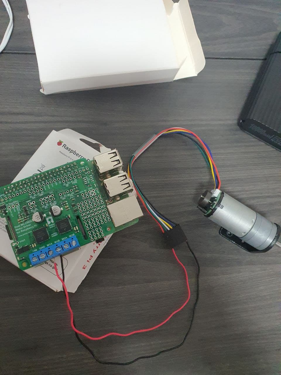
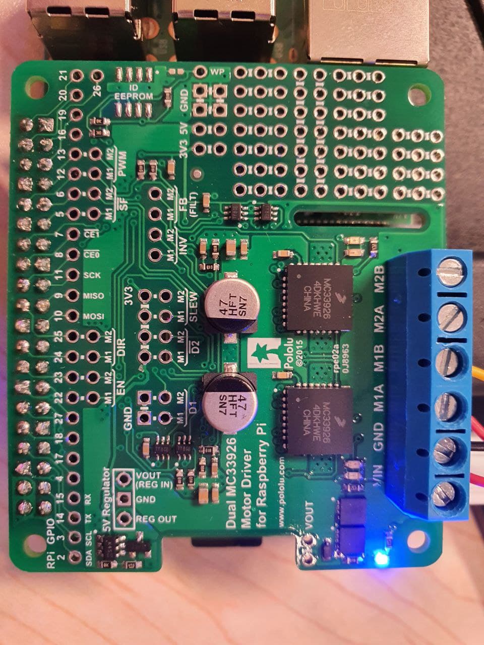
tried the unmodified example program in the python library (github) with no load attached. Yet i do not see any green or red motor indicator its only a blue led light. As for the pictures below, it is not connected but i just wanna show the setup. im using an DC motor with encoder, only connected with the motor power and ground.
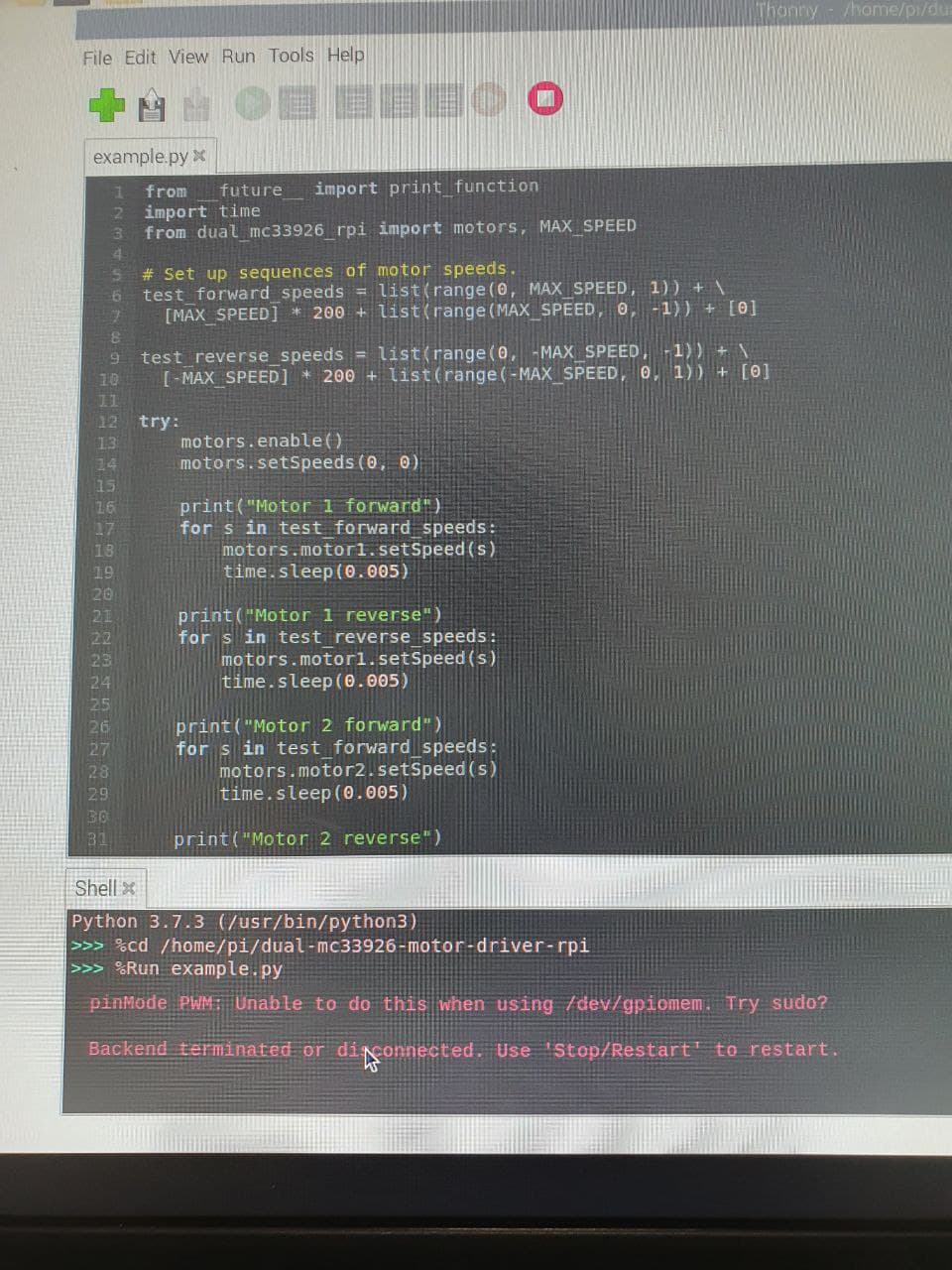
Currently have another problem where as errors comes in after i tried running the code.
Can you try using the command we suggest in the library readme to start the example program:
sudo python example.py
If that gets rid of the software errors but the indicator LEDs continue not doing anything, can you try monitoring the PWM pins with an oscilloscope and post some close-up pictures of your solder connections? Also, please include a picture showing your power supply connected.
By the way, your picture shows a motor connected to the driver, but I suggest testing your driver without the motor until we start seeing the indicator LEDs react to your program.
- Patrick
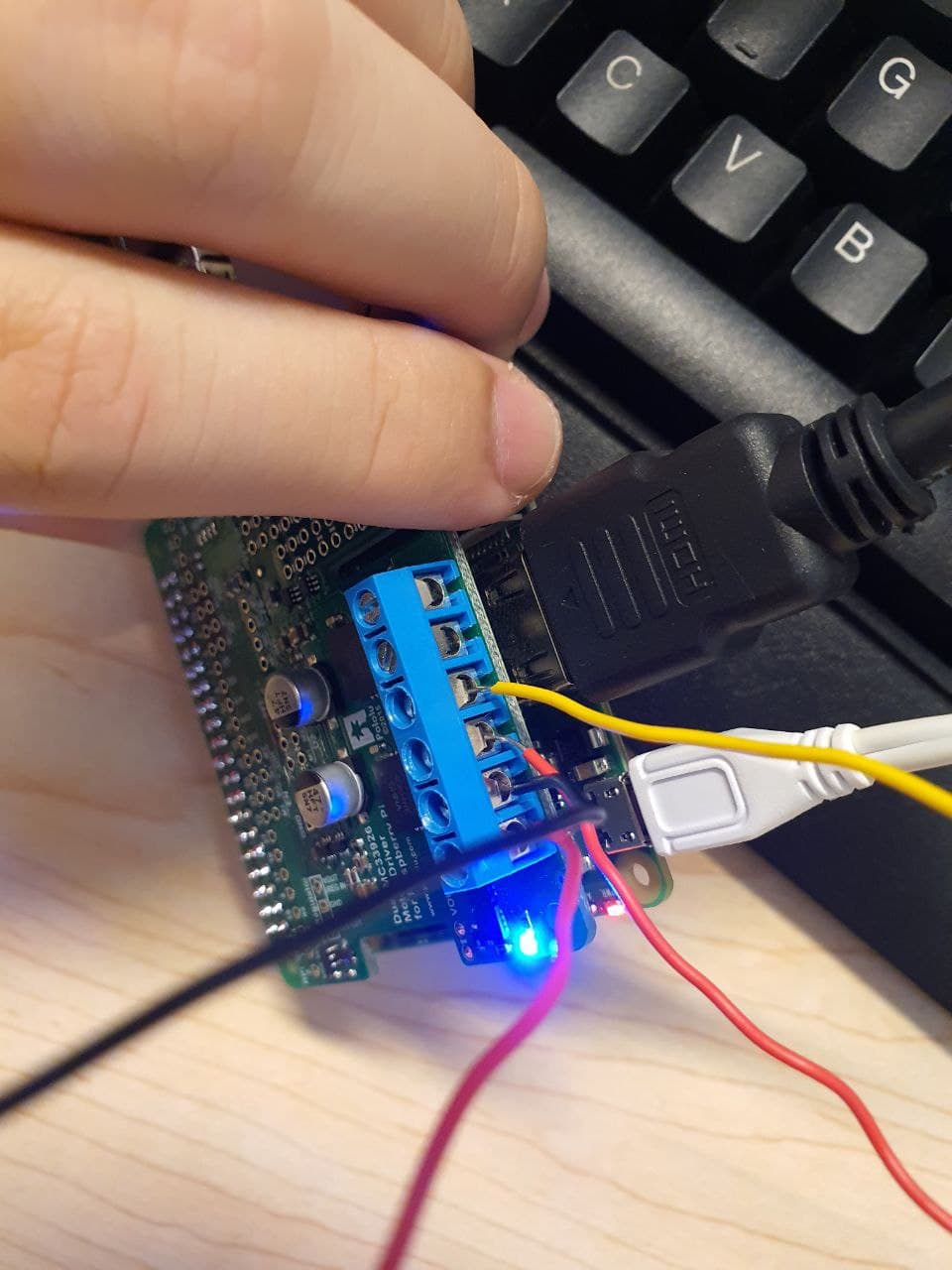
The software Errors has been solved. but the LED indicator as you can see in the picture below still lights up blue only(its currently running the code). power supply has been connected.
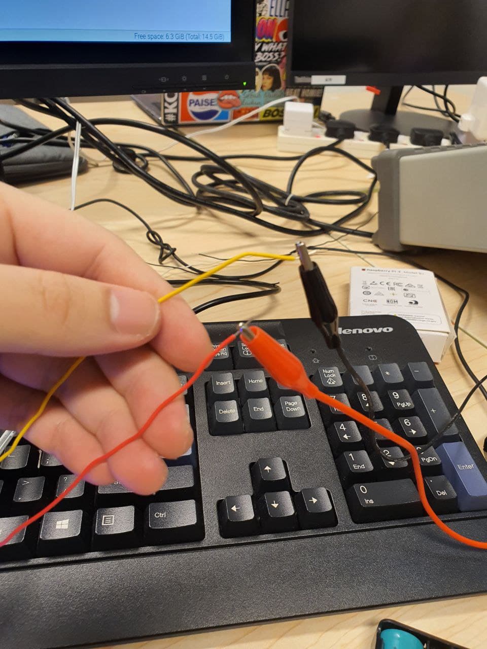
oscilloscope has been connected to MA1 and MB1 to see the voltages. Im not quite sure what u meant by the PWM pins? do you meant by the motor PWM Pins? or the motor driver MA1 and MB1?
pictures below shows -0V oscilloscope
Soldering connections close up pictures!
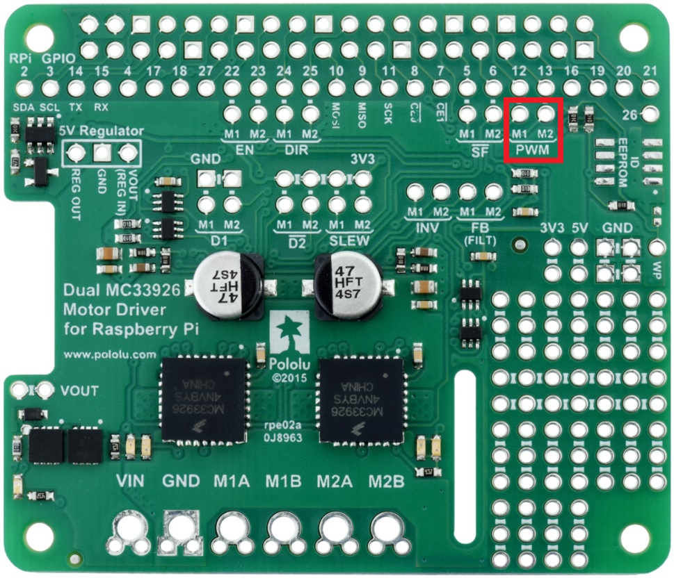
I was referring to the pins on the board labeled “PWM”; here is a picture pointing them out:
(Though it would probably be good for you to look at what all the control pins and output pins are doing so you can get a better idea of what is actually going on.)
By the way, it seems like you might have the ground clip of your oscilloscope connected to one of the driver outputs, but that should never be connected to anything besides ground. Connecting the ground clip to a motor output could damaged your probe or scope. To measure motor outputs, two scope channels should be used with the each probe connected to one motor output pin and both ground clips connected to the driver’s ground.
- Patrick