I want to use this #2804 relay to shut down a gas engine once the r/c futaba receiver loses connection with the transmitter. I tried to follow the instructions for learning mode and inversion but I can’t seem to ground the engine once I shut the transmitter off. Do you guys know what I am talking about? Any direction you could give me with this?
edit:#2804
You might try checking to see if your RC receiver is defaulting to outputting some non-neutral signal when it loses its connection with the transmitter. If this is the case, the RC switch with relay has no way of knowing that these particular signals should be ignored, since they look the same as valid signals.
An easy way to test this is to unplug the receiver wires and see if it gives a different result from the one you are describing.
Brandon
I disconnected the battery going into the receiver and still did not ground the engine.
When I have the transmitter and receiver on I see the led flashing quickly, then when I turn off the transmitter only the led flashes slower. So I know there is a different
I am using the assembled model and it does this with default or customized learning.
Any more ideas? I’m not really that good with electronics.
Could you try measuring the output of the “OUT” and “GOOD” pins on the RC switch in both cases (with and without your RC transmitter sending valid signals)?
Brandon
What do I measure on both of those? Simple as just hooking up a multimeter?
Yes, you should be able to use a multimeter (with the positive probe on the pin and the negative probe on the ground pin). The GOOD pin should measure 5V or the VRC voltage (whichever is lower) when the board is receiving a valid RC signal, and 0V otherwise. Similarly, the OUT pin will measure high when the relay is active (i.e. the relay coil is energized).
Brandon
Thanks for your help Brandon
I found 5V on the GOOD pin and 0V on the OUT pin with the transmitter on
Once I turned the transmitter OFF, there was 0V on the GOOD and 0V on the OUT
Seems like its not activating the relay, but the LED does change as stated above.
Anything else I can try?
It sounds like the RC switch is working as expected since the output is off when the signal is lost. It sounds like you want the relay connection made when the signal is lost. If that is the case, you should be able to get this kind of behavior by connecting to the NC (normally closed) pin on the relay board, and redoing the learn mode to get the behavior you want when the transmitter is connected. If you try doing it this way and continue to have problems can you post pictures showing how you have everything connected?
Brandon
I changed the connection and now have one wire connected to NC and one wire connected to COM. I cleared all setting, entered learning mode and kept the transmitter and receiver powered the whole time before saving the learning settings.
Now the outputs are grounded regardless of if the transmitter is on or off. I have to disconnect one of the ground wires to be able to start the engine.
Should I be doing the learning mode with the transmitter off so it tells the relay to flip to NC?
When you power on the relay what is the default position? I guess I am confusing myself on what Normal means and what it takes for the relay to move.
I need
COM and NC to be connected when the transmitter is off (receiver not sensing transmitter) and
COM and NO to be connected when the transmitter and receiver are both powered on.
Thanks for all the help Brandon
Can you describe the procedure you are going through when you do the learning mode (e.g. how are you controlling the channel on your RC transmitter that is being used with the RC switch during the configuration procedure)?
When you go through the learning mode procedure to configure the threshold value, the device will calculate the minimum and maximum pulse widths seen during that phase and set the threshold equal to the point midway between them (the average). It sounds like when you turn your RC transmitter on, the pulse width being sent is still below the calibrated threshold. By default, the relay is only activated when the pulse width being sent is above the calibrated threshold; however, note that the 5th step of the configuration procedure lets you chose whether or not to enable inversion, which will flip the logic so the relay will be on when the pulse width being sent is below the calibrated threshold.
Brandon
Brandon sorry for being difficult…I thought I wouldn’t have too many issues with this. Thanks again for helping
I actually don’t know what to do to control the RC input during the learning mode. I have been turning the transmitter and receiver on with the 2804 relay plugged into the 3rd receiver channel, with servos in channel 1 and 2. Any ideas on what to send to the RC input during learning mode?
I have tried inversion without any luck too.!
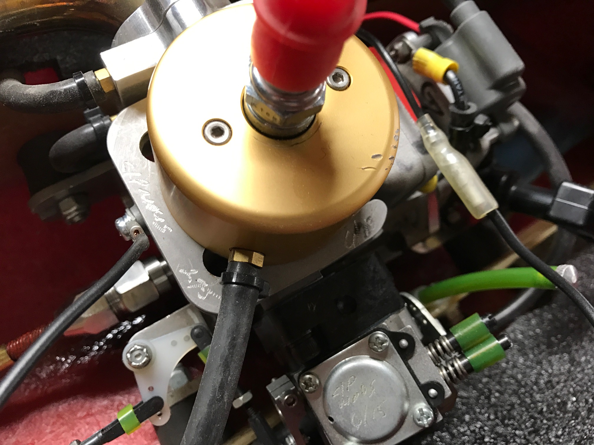
This pictures shows 3rd channel plugged into relay
Follow the black/red/white to GND/VRC/RC IN
And the black wires from the NC/COM going to the engine
These are the two black wires going to the engine.
The left side shows the wire screwed into the engine
And the right sides shows the bullet connector to the engine coil.
When the relay is closed (connecting NC/COM) the engine will ground into the coil.
I need the relay to be connecting COM and NO while the transmitter is on.
What signals you send to the #2804 during learning mode mostly depend on how you plan to use the channel that you are connecting as an input into the #2804 (channel 3, in your case). For example, if channel 3 is a throttle joystick (like it is on some transmitters), and you do not plan to adjust the throttle at all in your application, one way to do this is to set the throttle all the way down to 0% before entering the pulse-measuring phase of the learning mode. Then do not adjust the throttle and save the threshold. After that, during operation, so long as you keep the throttle in any position noticeably above its lowest point (e.g. like 50%), you should be sending a signal that the device recognizes as active and that should enable the relay and connect COM to NO.
Note that this would work the opposite way if you also enable inversion: adjust the throttle to a high value like 100% before entering the pulse-measuring phase of the learning mode. Then while you are operating the engine, you can keep the throttle low, like at 50% or 0%.
If you explain in more detail what kind of interface is on channel 3 on your transmitter, and what kind of behavior you plan for that channel during operation of your engine, we can make a more specific recommendation on how to set up your relay.
-Jon
Hi Jonathan thanks for helping. I think I get what you are saying about the 3rd channel. I am using the Futaba 2.4 faast 3PM-X shown here (link below). The 3rd channel uses a sliding on/off switch shown to the right of the wheel above the trigger. When adjusting the 3rd channel function, I can set the %
What I need is when the TX turns off or the RX is not accepting a signal from TX (disconnection between TX/RX) the COM and NO are connected. Is this something I can do with the #2804? I read somewhere that I could use it for this purpose. I don’t want to have to manually adjust anything while operating the TX to switch the relay if you know what I mean (other than the initial setting before I run the boat)
https://www.futabarc.com/systems/futk2021.html
I just noticed that your connections are not correct for the behavior that you want (they are basically backwards). You should connect your engine in a way that it is disabled when COM and NC are connected and enabled when COM and NO are connected.
To directly answer your question, yes, although channel 3 on your transmitter is different from what I described in my last reply, the #2804 should still be able to use it as an input to get the behavior that you want. Also, you probably do not need to do any adjustments to that channel to get it to work well.
After you make the changes to your relay connections, please do the following:
- Flip the channel 3 switch to the left.
- If it is not already connected, connect channel 3 on your receiver to the #2804.
- Get the #2804 into learning mode.
- Save the threshold. (Do not move the channel 3 switch.)
- Power off the #2804 to exit learning mode and remove the learning mode jumper connection.
- Flip the channel 3 switch to the right.
- Power the #2804 and try controlling your boat.
If that does not work, you might try starting the procedure again by pushing the button to the right first, instead of to the left. Then, during operation you should keep the switch to the left.
-Jon
Sorry, I just remembered that these RC switches have a safe-start feature, which makes it so that the procedure I replied with will not work. Having this safe-start feature means that every time you begin to operate your boat, you will have to move the switch from its off position to its on position. Actions to take during learning mode change as well. Accordingly, I rewrote my instructions below to reflect that. Can you try following them, instead?
- Flip the channel 3 switch to the left.
- If it is not already connected, connect channel 3 on your receiver to the #2804.
- Get the #2804 into learning mode.
- Move the channel 3 switch to the right.
- Save the threshold.
- Power off the #2804 to exit learning mode (the learning mode jumper connection should be removed at this point).
- Flip the channel 3 switch back to the left.
When you are ready to control your boat, power on the transmitter, receiver, #2804, etc. and then flip the channel 3 switch from left to right, and then back to left. It is important to flip that switch from its off position to its on position every time you are about to control the boat. By flipping it back and forth a few times, you can determine which position is which.
-Jon
Thanks for the step by step, I will give it a try… I just have one question, what do you mean by remove the learning mode jumper connection in Step 6? I thought in Step 5 it would save by inserting and removing the jumper.
You are right: inserting and removing the jumper saves the threshold. I edited that line to better reflect what I had intended, which was a reminder that the learning mode jumper connection should be removed at that point.
-Jon