Pololu 36v4 Stepper Motor Driver w/ Arduino Nano Every

Hello,

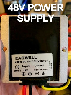
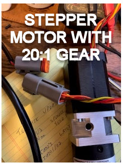
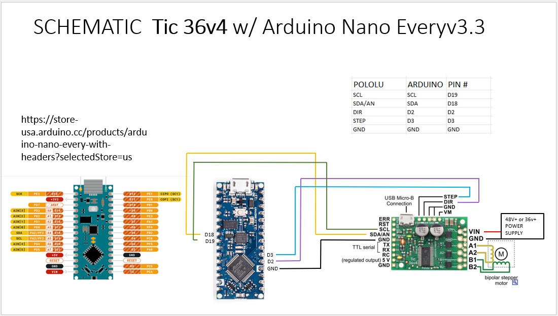
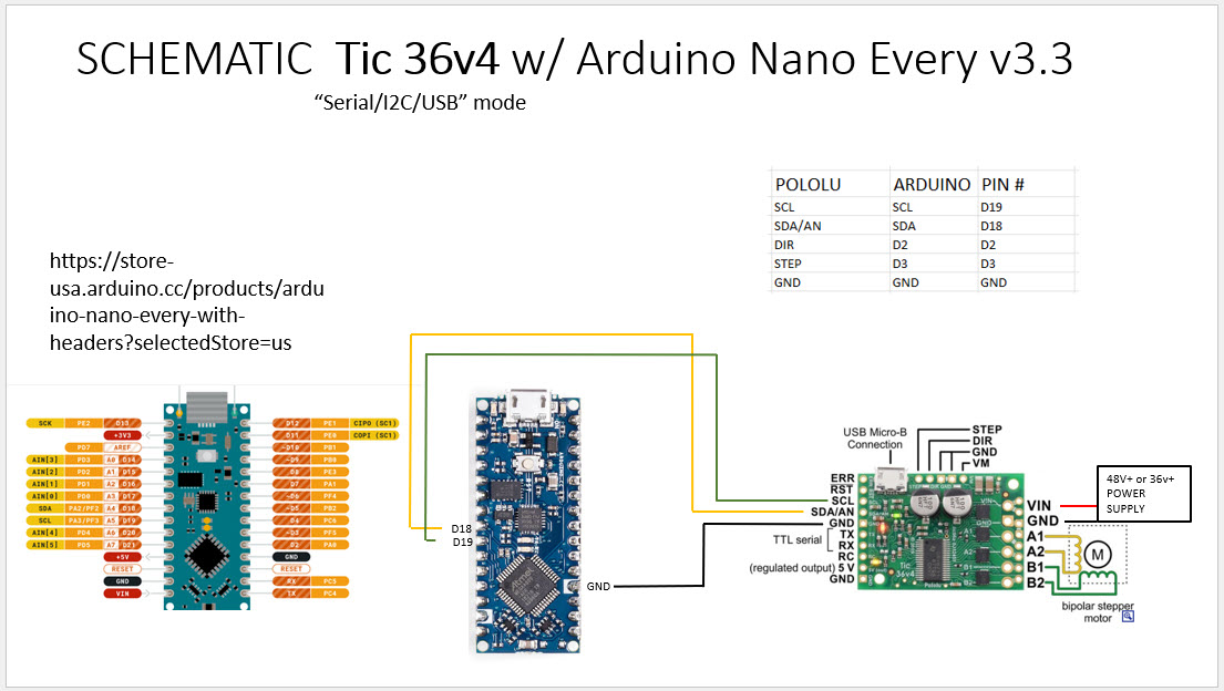
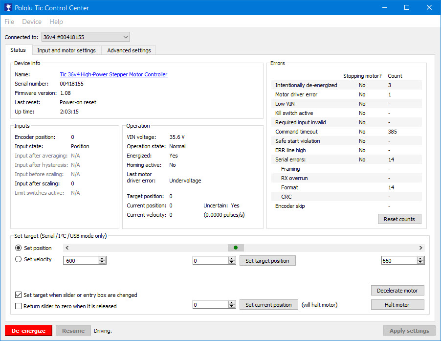
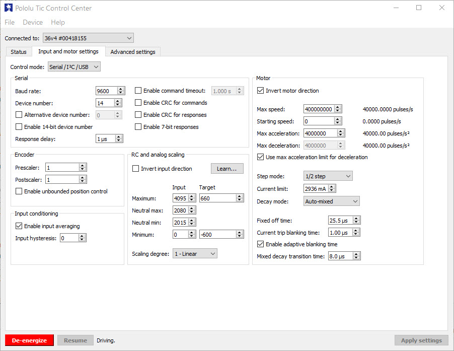
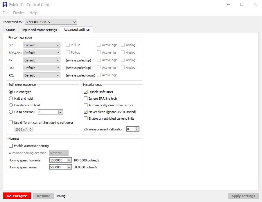
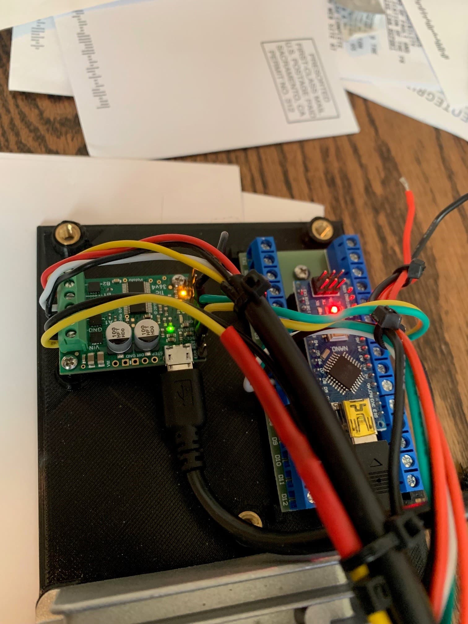
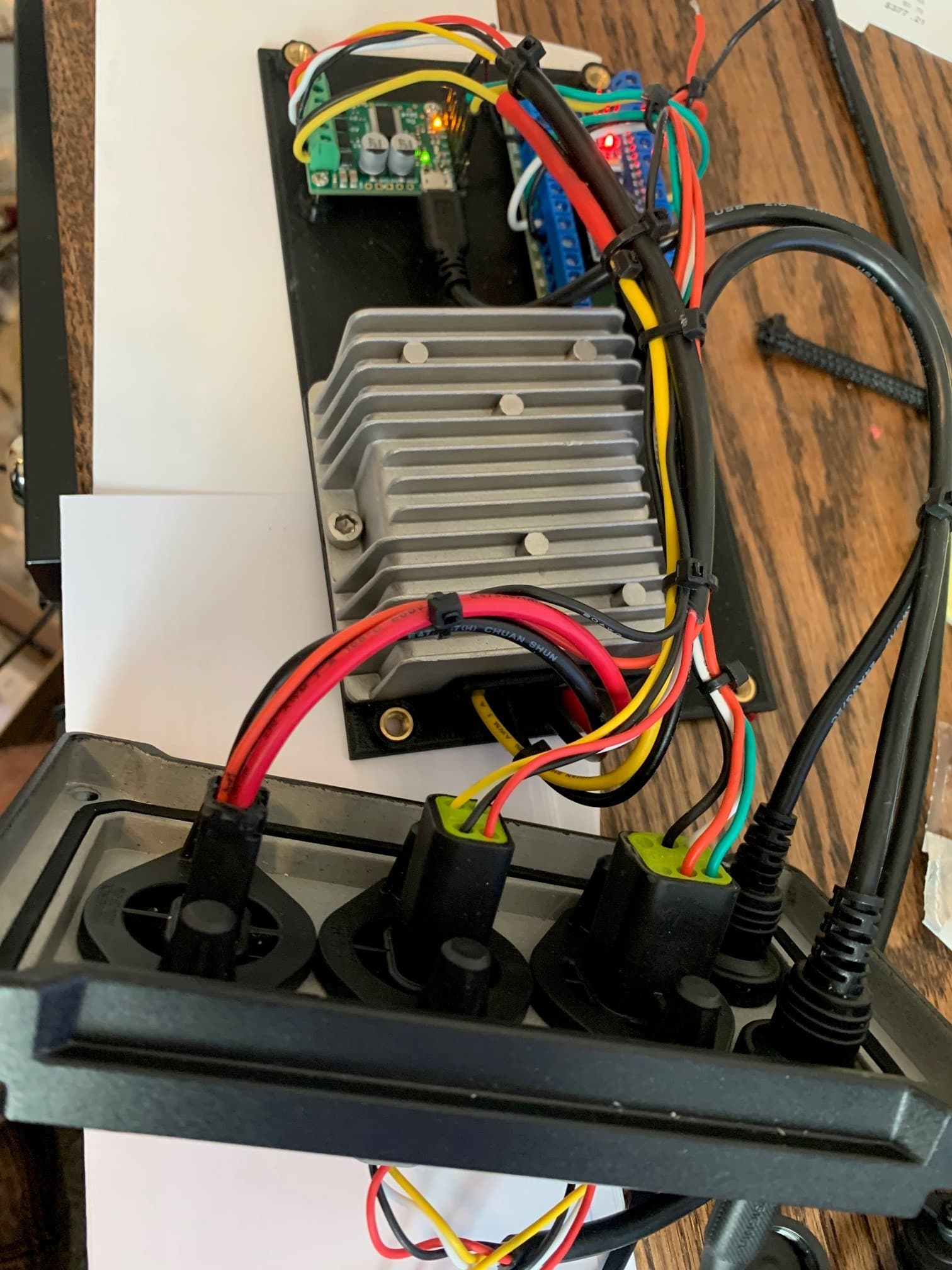
Any help would be greatly appreciated. I’m having trouble getting my stepper motor setup working. When stepper is connected it start to make a terrible sound so I disconnected it as fast as possible. After disconnecting the motor and measuring for voltage across A1-A2 (not sure if this is possible/correct way to measure voltage out to motor??) reading shows constant 48v. Dead constant voltage, no fluctuation in the reading at all, Measuring across B1-B2 shows a few mV.
I started with the basic stepper motor package from Pololu on Github. In the Arduino sketch I did increase the StepPeriodUs value (to as much as 1000000) to try and slow it down to give the meter a chance register the voltage change, but to no avail. I also added Serial.begin( 9600 ); and some Serial.println( “ROTATE 1” ); code to try and get a visual thru the serial monitor of how fast the steps were being executed. Also learned nothing there.
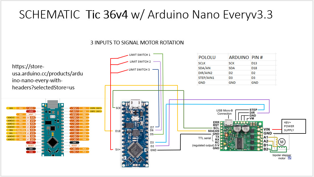
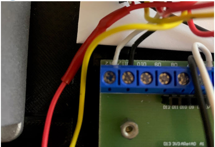
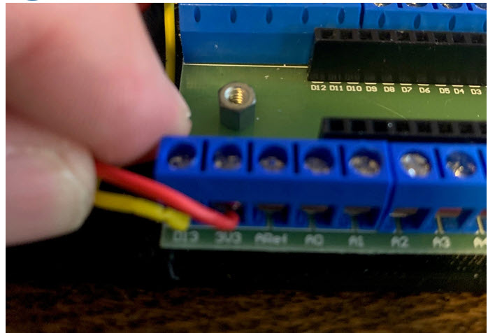
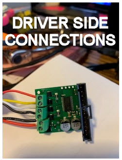
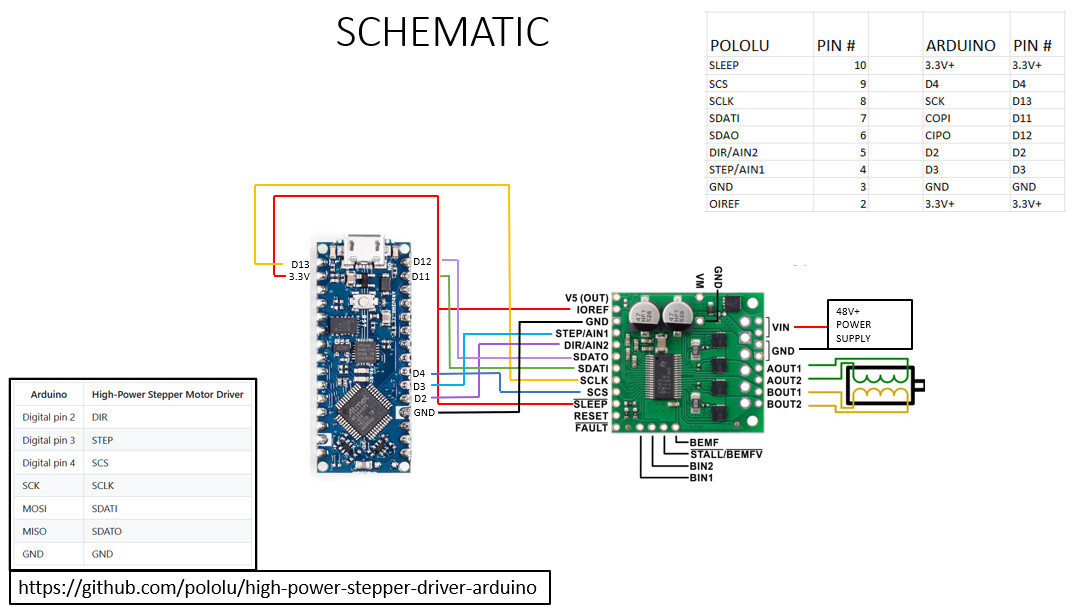
Please see Schematic and Arduino Sketch below

Again, thanks for any advise, newbie appreciates it.

// This example shows basic use of a Pololu High Power Stepper Motor Driver.
//
// It shows how to initialize the driver, configure various settings, and enable
// the driver.  It shows how to step the motor and switch directions using the
// driver's SPI interface through the library's step() and setDirection() member
// functions.
//
// Since SPI is used to trigger steps and set the direction, connecting the
// driver's STEP and DIR pins is optional for this example.  However, note that
// using SPI control adds some overhead compared to using the STEP and DIR pins.
// In addition, since the library caches SPI register values, SPI control is
// more likely to re-enable the driver with the wrong settings (e.g. current
// limit) after a power interruption, although using the verifySettings() and
// applySettings() functions appropriately can help prevent this.
//
// Before using this example, be sure to change the setCurrentMilliamps36v4 line
// to have an appropriate current limit for your system.  Also, see this
// library's documentation for information about how to connect the driver:
//   http://pololu.github.io/high-power-stepper-driver

#include <SPI.h>
#include <HighPowerStepperDriver.h>

const uint8_t CSPin = 4;
const uint8_t DirPin = 2;
const uint8_t StepPin = 3; //ADDED

// This period is the length of the delay between steps, which controls the
// stepper motor's speed.  You can increase the delay to make the stepper motor
// go slower.  If you decrease the delay, the stepper motor will go faster, but
// there is a limit to how fast it can go before it starts missing steps.
const uint16_t StepPeriodUs = 10000; //CHANGED

HighPowerStepperDriver sd;

void setup()
{
  Serial.begin( 9600 ); //ADDED
  SPI.begin();
  sd.setChipSelectPin(CSPin);

  // Give the driver some time to power up.
  delay(10); //CHANGED

  // Reset the driver to its default settings and clear latched status
  // conditions.
  sd.resetSettings();
  sd.clearStatus();

  // Select auto mixed decay.  TI's DRV8711 documentation recommends this mode
  // for most applications, and we find that it usually works well.
  sd.setDecayMode(HPSDDecayMode::AutoMixed);

  // Set the current limit. You should change the number here to an appropriate
  // value for your particular system.
  sd.setCurrentMilliamps36v4(500); //CHANGED

  // Set the number of microsteps that correspond to one full step.
  sd.setStepMode(HPSDStepMode::MicroStep32);

  // Enable the motor outputs.
  sd.enableDriver();
}

void loop()
{
  // Step in the default direction 1000 times.
  sd.setDirection(0);
  for(unsigned int x = 0; x < 10; x++)
  {
    sd.step();
    delayMicroseconds(StepPeriodUs);
    Serial.println( "ROTATE 1" ); //ADDED
  }

  // Wait for 300 ms.
  delay(2000); //CHANGED
  Serial.println( "DELAY 1" ); //ADDED

  // Step in the other direction 1000 times.
  sd.setDirection(1);
  for(unsigned int x = 0; x < 10; x++)
  {
    sd.step();
    delayMicroseconds(StepPeriodUs);
    Serial.println( "ROTATE 2" ); //ADDED
  }

  // Wait for 300 ms.
  delay(2000); //CHANGED
  Serial.println( "DELAY 2" ); //ADDED
}

Hello.

While the driver is stepping, I expect the voltage on the motor output pins to vary, but without the motor connected, the actual voltage readings won’t mean much since it is trying to current limit with no load.

What are you using for your power supply? Your operating voltage (48V) is very close to the driver’s maximum operating voltage of 50V, so that does not leave you very much margin. For example, if you’re using a battery, it could easily reach higher than 50V when fully charged. Even if you’re using a something more regulated (like a benchtop supply), you might have problems with spikes from the motor or noise on the line. If it’s practical for you to use a slightly lower voltage, I recommend doing so.

It looks like you also modified the code to only take 10 steps in each direction. Please note that the code sets the microstep mode to 1/32. For reference, if your stepper motor is 200 steps per revolution, 10 microsteps at that resolution would be something like °0.5 or °0.6. So, it might be working fine, but hard to see. While testing, could you try changing the microstep mode to full-step and have the code step 1 full revolution? You can do this by changing sd.setStepMode(HPSDStepMode::MicroStep32); to sd.setStepMode(HPSDStepMode::MicroStep1)) in setup() and changing the FOR loops in loop() to for(unsigned int x = 0; x < 200; x++), if your stepper motor is 200 steps per revolution.

If you still have the same problem after making those modifications, could you post pictures of your setup showing all of your connections? A video showing the problem would probably be useful as well.

Brandon

Hello,

Brandon, it looks like you may have looked at this post. A little more info since last night, after digging around this forum and Adruino’s I learned that this driver does not have non-volitile memory and the parameters must be reloaded after each power off. For this application power will be cycled regularly. I found the Tic version of the same driver that does have memory and will retain the parameters for power-up. I placed an order for two of the TIC version last night, they will be here tomorrow.
With the first driver I did have a bit of trouble translating the pin-out from the Arduino-compatible #3104 A-Star 32U4 Mini SV shown as an example. I did find a schematic of this driver connected to an Ardunio Uno but as this is all new territory I likely made a mistake on the pin-outs and either put the driver into FAULT or damaged it. Perhaps you can verify the new schematic below.

Question:
How can I measure the A1 A2 B1 B2 outputs with a multi-meter before connecting the motor to validate before drawing current?

Thanks Again!!

Hi Brandon,

you replied while I was updating post.

Power supply is 12v input 48v (47.8v measured) output found on amazon. I also have one from MPJA, it has adjustable input and out put voltage. 12v supply is bench top adjustable. up to 3amps.

Stepper Motor is Nanotec ST4118D3004-A. Just reread the data sheet, voltage per winding does not jive with graphs and conversation I had with sales guy. Data sheet says 3.3v graphs and sales said either 24v or 48v. I need to call them. If its 3.3v I’m screwed, different driver, different voltage supply, Sunday is coming quick.

I will make the changes to the sketch and try yo measure voltage without connecting the motor. Need to learn what I can here.

Thanks Brandon!!

Hi Brandon,
So I have a little more information, pics below and a link to a video showing my solder connections. I contacted sales at Nanotec and the motor can take anywhere from 3.3 to 48v. Pheew!! Performance is better with higher voltage.
I did have one more 36v4 (non-Tic) on hand, so hooked that one up to see if I had damaged the other driver. Before connecting the motor I had steady 47v on both AOUT and BOUT. After connecting the motor it made the same grindy noise and I quickly disconnected the motor, maybe connected for 1 second max. Now there is still 47v on BOUT but nothing on AOUT, first board AOUT had 47v and nothing on BOUT, either case the motor does nothing. There is a 20:1 gear reduction on the motor as well, guess it could be moving and not seeing it but the no voltage on either AOUT or BOUT tells tells me something is wrong. novice question, is AOUT for one direction and BOUT for the other? Could the driver be in fault mode? How can I reset it? Next I disconnected the 47v power supply and connected the bench top to the driver and set voltage to 12v. Same results.

I also changed for(unsigned int x = 0; x < 10; x++)
to
for(unsigned int x = 0; x < 200; x++)
for one revolution, which would be 1/20 of a rev after the gear reduction
I will try
for(unsigned int x = 0; x < 2000; x++) for a half revolution at the final output
and use
const uint16_t StepPeriodUs = 500; for faster speed.

Pics below
Link to video
Click to Download

Thanks Brandon!!

48 V POWER SUPPLY BOTTOM
BENCH TOP PS
CONNECTOR


DRIVER SIDE CONNECTIONS
STEPPER MOTOR WITH 20-1 GEARBOX
SWITCH PLATE

One more thing I just found.

With the motor Disconnected:
AOUT1-OUT2 measures 0v
BOUT1-BOUT2 measures 12v constant (same as input voltage from bench top PS)

Motor Connected:
AOUT1-OUT2 measures 0v
BOUT1-BOUT2 measures 0v

Maybe its in fault mode??

You’ve covered a wide variety of topics in your last few posts, so my response might jump around quite a bit, but there are parts of each that I wanted to address.

You mentioned taking measurements with and without your stepper motor; it is not clear if you were powering down the system in between, but just in case, please note that connecting or disconnecting a stepper motor while the system is powered can destroy the driver, and more generally, rewiring anything while it is powered is asking for trouble.

As you mentioned, the High-Power Stepper Motor Driver 36v4 needs to be configured via SPI on each power up. In the example programs, this is done in the setup() function, so it happens automatically when the microcontroller is powered too. The Tic controllers can be configured via USB and those configuration settings are stored in non-volatile memory. However, please note that you cannot use the I2C and STEP/DIR interfaces at the same time (as implied by your wiring diagram). You can either configure the Tic in “Serial/I2C/USB” control mode and use TTL Serial or I2C commands or use the “STEP/DIR” control mode and use the STEP/DIR pins directly. When in “STEP/DIR” mode, you will be bypassing the Tic’s onboard microcontroller, which will mean some configuration settings will also be ignored (such as the speed and acceleration limiting settings). Aside from that, your diagram also has SCL pin on the Tic connected to the SCK pin on the Arduino Nano Every, instead of the SCL pin, which should be digital pin 19 (D19). Also, I recommend simplifying by removing the limit switches until you get it working.

For the stepper motor, as long as you are using a current limiting stepper motor driver or controller (like the ones we carry), you can use a higher voltage than the stepper motor is rated for. Doing so has some benefits as the motor is able to ramp the current up faster, allowing for higher achievable step rates.

Thank you for the video; the soldering looks pretty good! It is hard to tell from your pictures how the stepper motor wire are connected to the driver, but you should double check that the correct pairs of wires are connected to each motor output. The datasheet from the page you linked to shows the brown and orange wires as one pair, so those should be connected to the same motor output channel (e.g. AOUT1 and AOUT2) and the yellow and red wires are the other pair and should be connected to the other motor output channel (BOUT1 and BOUT2).

As I mentioned before, reading the voltage across the motor outputs with nothing connected is not very useful since the controller is trying to limit the current and it cannot do that without a load attached. Additionally, the current (and therefore voltage) will vary depending on which microstep index the driver is currently on. Ultimately, to test the driver, it would be better to measure the current through one of the motor coils while the motor is energized but stationary. The code you posted before enables the motor at the end of setup(), so you can comment out everything inside the loop() function if you just want to enable the stepper and take a measurement of the current through one of the coils without it moving. Please note that the High-Power Stepper Motor Driver 36v4 defaults to the maximum current limit when powered up (~18 A), so if you measure something higher than what you are configuring the current limit to in your code, you should power it down immediately, as that indicates something went wrong and the current limit was not set. It looks like your motor has a current per phase rating of 3A, and you are setting the current limit to 0.5A. You might consider increasing that to something closer to 3A, especially since your stepper motor has a gearbox attached that could be making it harder to start up.

It sounds like you’re mostly concerned about the noise the stepper motor makes. If the motor is making a concerning noise, the outputs must be doing something and it is unlikely it is triggering a fault (since a fault disables the motor output). Could you post a video showing the problem(s)?

Brandon

Hi Brandon,

Motor connected vs disconnected: Yes always powered down for disconnect and re-connect of motor. Arduino also. Absolutely never connect or disconnect anything while powered up. Do have just enough experience with electrical to know to follow that rule.

Please see new diagram for “Serial/I2C/USB” I think it would be set to use the speed and accell limits. → these connections are where I get lost, please verify. Thank you!

I did not find a specification but I believe the max voltage for this motor is 48v. I did order another power supply that output 36v max 5A that I can easily swap out. It sounds like backing off of the 50V max is a good idea. Don’t think it will make any noticeable difference in performance for this application. Is is a shift by wire system for a houseboat, each of the three switched correspond to FWD - N - REV. Motor will only need to rotate enough to rotate output shaft of gear box 15degrees to shift from one to the other. Might go back and forth 25-30 times while parking the boat then sit for days powered off.

Thanks for the compliment on the soldering, i do spend time to try and get those clean. I do have a desktop adjustable temp iron with a variety of tips so there is no excuse for poor solder connections.
Yea, I jumped the gun making the wires to final length from the get-go, should have known better. I will leave long leads for initial connection on Tic version.

Have double checked and re-double checked connections to motor.
Black at driver to motor brown
White at driver to motor orange
Yellow at driver to motor yellow
Red at driver to motor yellow

Measuring output:
I will follow your suggestion, will take some wiring changes to connect meter.

Current setting in code:
Yes i dropped that down to try and protect against over current if I have something wrong. I will try 3A. Keep in mind Tic board shows up today, I will be switching to that anyway.

Motor Noise:
I only got motor noise on initial power up with new (non-TIC) 36v4 controllers. subsequent power-ups after changing code for longer dwell between steps, for loop to change number of steps, etc make no difference. Get nada from motor, this makes me think I hurt something.

FYI:
My power up sequence–> after all connections complete, power up Arduino(power via USB), power up controller (12v desktop PS), re-send sketch to Arduino.
Power Down → disconnect Arduino USB, power down 12v bench top PS.

Questions here: 1. is that correct? 2. In-use I was planning on power up for both at the same time i.e same 12v supply to both. Should I add a relay to the Arduino and power up driver after a dwell? or power up the driver first?

Have learned a lot last few days, many many thank once again! I will be setting up Tic driver ASAP, please see new schematic below.
If I understand it correctly, this will have the driver operate in “Serial/I2C/USB” mode, this means it will remember settings from the sketch in the Arduino for future power-up. I have not yet seen the sample sketches, I will download from github right away.

Hi Brandon,

The Tic36v4 drivers showed up yesterday, after at thorough read of the Tic documentation Pololu - Tic Stepper Motor Controller User’s Guide I have better understanding of the different modes it can run in and how to choose and configure for each. Learned a lot with the other board but do wish I had found this one first, 100x easier for first-timers to get something going.
I set it up for “Serial/I2C/USB” mode and got the motor turning, adjusted speed, acceleration and scaling to get the motion I need thru the Pololu Tic Control Center. Really fantastic interface.
These are my connections, see schematic below, note earlier schematic had D18 shifted up by 1 pin, corrected now.
Tic36v4 SCL to Arduino Nano SCL D18
Tic36v4 SDA/AN to Arduino Nano SDA D19
Tic36v4 GND to Arduino Nano GND (on Digital side of Nano)

I am having trouble with the sample sketches though, something seems to get hung up on the “delayWhileResettingCommandTimeout(xx);” command.

I2CSpeedControl sketch:
// Move forward at 200 steps per second for 2 seconds.
tic.setTargetVelocity(2000000);
delayWhileResettingCommandTimeout(2000); → hangs up here
changing delayWhileResettingCommandTimeout(2000); to dwell(5000); works fine,
As typing I just realized I need to look at the sample provided.

For what I need I can just use this but something is not right. For this application I will be able to use a slightly modified version of the I2CPositionControl.ino sketch, based on which switch is closed I will just call one of three positions, Little work on the sketch should do it. Its not finished but my modified version is attached.
You will see I added the tic.setProduct(TicProduct::Tic36v4); command and tried setting the current limit. Again what I have there works but not sure its correct.

Thanks Brandon!!

Pin_6_REV.ino (3.1 KB)

.

Hello.

I’m glad you’ve had a positive experience with the Tic controller so far.

I am not familiar with dwell(), and I do not see it in the code you posted; is that a custom function you wrote?

With the Tic’s default settings (e.g. if you have not disabled the command timeout feature) I would expect the modifications you made in your example program to result in a command timeout error after 1 second (i.e. before delay(1500) finishes). You can find more information about the command timeout error in the “Error Handling” section of the Tic user’s guide. Does the red LED on the Tic light up when you run your code (indicating an error)? It looks like the code you posted still uses the delayWhileResettingCommandTimeout() function at the end of loop(); is that also hanging?

Brandon

Hello Brandon,
Pardon the delayed response, have been having some success and some challenges. It looks like the challenges may be related to you latest response on the command timeout. But maybe not??? Im a bit stumped on this one.

Correction on dwell(), getting NC code mixed up, should be delay().

I think the best place to start now is to look at the latest code, I am having an odd issue where when the ‘currentLimitWhileMoving’ variable is set to anything over 600mA (I need 3000mA) the code will hang up and I have to reset the Arduino, and reset the 0 position. I believe the issue is in the code somewhere because the stepper still moves without issue when commanded thru the Pololu Tic UI interface.
It seems odd to me that changing just the value of ‘currentLimitWhileMoving’ has an effect on how the code runs. You will see in the code that I added a variable to control if info is sent to the Arduino Serial Monitor or not. I was testing with different delay() values to see if maybe the hanging code has something to do with timing of serial monitor command and subsequent commands to the Tic. That does not seem to be relevant, but I can neither confirm or deny without question. Part of what lead me to this logic is that I do see Serial Errors in Format row in the Tic Control Center. Images attached.

Is the command_timeout necessary, this application is pretty basic, just need the motor to goto a pos when one of the switches is closed. It is physically impossible for any two switches to be closed at the same time as there is a lever arm that moves to close the switches one at a time. The only ‘complicated’ part is storing the ID of whatever switch is closed at power down so in the event the shift lever is moved while powered down, the stepper will move to the correct position when powered back up.

Many thanks for any advice you may have!

SWITCHES_4.ino (7.2 KB)


Hi Brandon, short follow up here. I did forget to put ‘#include wire.h<>’ in the code but that did not change the behavior. It the code still lock up randomly. With max current set to 700mA it lock up much less often but none the less, same problem. I did de-energize the motor and ran the switch combinations repeatedly without issue, the code itself seems to run fine, when the motor is being driven the code gets stuck. Is there a way to log the SDA/AN and SCL signals to get a clearer picture of what the Tic is doing? I am thinking the problem is one or more of the following:

  1. My 12v to 36v device is not producing enough current. How would the Tic36v4 behave if current was insufficient?
  2. Interference / induction on the SDA/AN and SCL wires. They do cross the 36v input, but are pretty short at about 3.5", 20awg silicone. I will separate where they cross and add an EMF jacket.
  3. Something wrong with the TIc36V4, unlikely but I have a spare. Last resort I will replace it.

Few pics of setup and wiring below.

Thanks Brandon!

yellow = SCL
green = SDA/AN

Assembly

Switches

Hello.

Could you try the following process?

  1. Connect your Tic to the Tic Control Center.
  2. Power up and run your system.
  3. Click the “Reset counts” button inside the “Errors” box on the “Status” tab of the Tic Control Center.
  4. Wait for the system to lock up.
  5. Take a screenshot showing which errors (if any) have a non-zero error count.

Your system locking up more when the current limit is set higher makes me suspect a power issue. If your power supply isn’t handling the current, the voltage on the Tic’s VIN pin would drop until it triggers a “low VIN” error (under 7V on the Tic 36v4). If you do not have USB connected (i.e. the Tic is only powered through VIN) it could drop low enough to cause a brown-out. How are you powering your Arduino board? If it is powered from the same source, you might check to see if it is resetting or getting stuck in some bad state as well (that could explain the serial format errors).

I briefly looked at your code; it has a lot going on which probably isn’t worth troubleshooting until we can determine if it is the culprit. Since we suspect a power or interference issue, could you try running the “I2CPositionControl.ino” example program from our Tic library? If we are right, you should still get the same issues with that simple example code. Please note that this code expects you to have set the current limit through the Tic Control Center beforehand.

Neither the Tic or the Tic Control Center has a built-in feature for logging the SDA/AN and SCL signals. You might be able to write your own program to do that, but ultimately it might be easier to just look at them with an oscilloscope.

Brandon

Thanks Brandon!
Below is a screen capture after locking up running my code. It did do the same thing running the I2CPositionControl.IO as well. For agruments sake I am going to replace the Tic with the spare and check for same results, in the mean time I will shop for a quality (not Amazon) 12v to 36v converter.