
So I am decent with electronics but new to this aspect, can anyone recommend me a servo controller that has user friendly software? I assume go USB over COM but you tell me. I want to be able to activate servos and relays/solenoids to drive motors and such from either a joystick or keyboard shortcuts (I will solder keyboard leads to sensors) and I will do this via remote desktop connection. I was looking at Parallax stuff and also Pololu I really don’t know (be honest) Thanks
I recommend that you get one of the controllers in our Maestro family of servo controllers. The Maestros come with a user-friendly graphical interface for configuring the servo controller over USB. The Maestros come in 6-, 12-, 18-, and 24- channel models. You can find them here: pololu.com/catalog/category/12
If you want to control servos on your Maestro using keyboard shortcuts or a joystick, you will have to write some software. There are many options, but probably the best way to do it (if you can learn C#) is to modify the MaestroExample program available in the Pololu USB SDK. See the Writing PC Software to Control the Maestro section of the user’s guide for more details.
Soldering sensors to keyboard leads sounds risky. Have you successfully done this before? I think most keyboards can’t handle more than 3-10 button presses at once. Also, you will probably be giving up the use of your keyboard on both computers while this program is running.
Here’s what you could probably do instead: you could use a Maestro to interface your sensors to your computer. All of the Maestro’s channel signal lines can be configured as analog or digital inputs (up to 12 analog inputs available). You could write a program that reads the voltages on those lines and sends commands to the remote computer using TCP. On the remote computer you could run a simple program the makes one of the Maestro’s serial ports available over TCP so you can send commands to the remote Maestro. Here’s a TCP-serial bridge that I just found; I haven’t used it but it sounds like it should work: elifulkerson.com/projects/te … bridge.php In that case you would only need to write software for the computer that has the sensors connected to it; you wouldn’t write any software for the computer with the servos.
–David
Lets say I went with a 6 channel USB controller and needed a few more channels, can I double another 6 within the same window/program buy simply plugging in another USB board or do I have to ditch my 6 and buy a 12?
I hate the sounds of that, C#? Is this like Visual Basics C++ because I have not toyed with it much.
I have never thought about the pressing multiple buttons at once cap. But I figured open/closed circuits could trigger things with leads, then again maybe not.
What do you mean giving up use of my keyboard?
Wait, these 6, 12, 18, & 14 channel controllers can be reversed to allow inputs? So your saying I can make a 6 channel become a 3 channel with 3 inputs/sensors and 3 outputs for relays/servos?
It depends what you want to do. The Maestro Control Center software that we offer can only connect to one Maestro board at a time, but you can run two instances of the Maestro Control Center and connect to both Maestros. If you are writing your own software to control the Maestro, you can connect to two different Maestros but it will complicated your software a bit.
C# is an object oriented language that is powerful but safer than C++. You can read about it here or just download the Pololu USB SDK and look at some of the code in it, such as MaestroExample (a simple GUI that connects to a Maestro and commands it to perform a motion sequence).
You said you would be using a keyboard to encode sensor readings as key presses. So if you try to switch windows and type something in to a different window, your hacked keyboard will start typing in to the new window, and you’ll see a bunch of characters appear that you didn’t type, right?
Yes. Any of the channels can be configured as a Servo, Input, or Output. For inputs/sensors, configure the channel as an Input. For servos, configure the channel as a Servo channel. For relays, configure it as an Output, but note that there is a 220 Ohm current limiting resistor and there are limits on how much current the Maestro can provide from its signal lines, so it probably won’t be able to directly drive a relay very well; you might need to add a transistor. We don’t have a 14-channel Maestro, but we have a 24-channel one.
–David
Sounds like it would get complicated to link the instances together in sync sharing tasks maybe I should go with a 12 to be safe.
I checked out some C# youtube videos and Visual Studio looks to be no harder than Front Page and some minor HTML.
Yes you did get me correct on the keyboard, but couldn’t I just use 1 channel to activate a relay between the keyboard and the PC disabling it so that it can not compete? Just thinking.
I meant to say 24*
I don’t know. I think you should try the using a Maestro to read your sensors because it will require a lot less hacking and we can help you if something doesn’t work when it should.
–David
Ok than, I shall purchase a 12ch from you guys tomorrow afternoon and hopefully the community here will help me with programming if someone shall have the time. I will obtain a copy of Visual Studio 2010 asap, this is a home security project instead of mounting cameras to my house I will have an indestructible moving chassis loaded with cameras that charges itself up off the sunlight mostly. It will monitor my yard day and night 
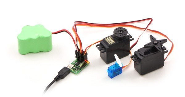
Ok I just placed my order! Can anyone explain what the PWM output is used for? And I see a picture with a Maestro that has a battery of some sort connected to what appears to be one of the channels, is this giving the servos extra power or something?
The PWM output feature available on the 12, 18, and 24 channel Mini Maestros lets you output one PWM signal with a very flexible frequency and any duty cycle between 0 and 100%. This could be useful for many things, such as controlling the brightness of an LED or controlling the speed of a motor (for a motor, you would require a motor driver).
If you have questions about what a pin on the Maestro does, please refer to the two sections of the user’s guide that explain the pinouts:
pololu.com/docs/0J40/1.a
pololu.com/docs/0J40/1.b
USB does not supply enough power for servos; the servos in that picture are solely powered from the battery.
If you need a small amount of power from the Maestro, you can use the +5V lines available on the Maestros. This might be suitable for powering your sensors, but probably not your servos.
–David
Sorry if I ask too many questions, so than why does the 18 and 24 have two servo power inputs? I noticed the 6 and 12 only have the power pins and not the blue screw type connectors the 18 and 24 have.
I get it now, the PWM is sort of like a low voltage RC speed controller. I take that all the other channels for servos are more less a “on” or “off” gate and in reverse or do they just have fewer voltage steps than the PWM?
I’m looking over that guide as much as possible before I ask questions now. Thank you
Oh and by the way, is there anyone willing to exchange some PayPal $ to help me with the C#? Easiest way to go is Visual Studio?
The servo power terminal blocks on the 18- and 24- channel Maestros allow you to supply more current to the servos than is possible with the smaller power input pins, but the small power input pins can be more convenient for some applications.
I don’t know why you said “PWM is sort of like a low voltage RC speed controller”. The Maestro’s PWM output feature does not allow the Maestro to receive RC pulses, and it can only control the speed of a motor if you add additional circuitry (i.e. a motor driver or at least a transistor).
The difference between the standard Servo channels and the PWM Output channel is that the standard servo outputs have a somewhat limited range of frequencies and a very limited range of duty cycles. Those limitations are described in the “Maestro Settings Limitations” section of the user’s guide: pololu.com/docs/0J40/9
Yes, the easiest way to go is Visual Studio. I recommend the free version, Visual Studio 2010 Express Edition C#.
–David
I managed to open the Maestro example in Visual Studio 2008 Pro. But I was hoping to be able to open the Maestro Control Center in Visual Studio because the “track bars” are already coded to each channel. If I had that code I would be halfway there then all I would need to do is code the joysticks axes and buttons to each track bar / channel, unless I am missing the point of the Maestro Example?
Were you able to compile and run the MaestroExample program? Did it succeed in moving your servos? I think it’s programmed to periodically move a servo connected to Channel 0 when you check the motion sequence checkbox.
You don’t need a track bar to set the target of a servo on the Maestro. The MaestroExample program that you opened demonstrates how you can maintain a connection to a Maestro and send native USB Set Target commands regularly. You should find the part of the code that calls the setTarget method of the Usc class, read the code, understand it, and then modify it to send the value from a joystick instead of the arbitrary sequence of values it is currently programmed to send.
–David
I honestly am still waiting for shipping  trying to get a head start so I am ready for when it arrives. I used the first class mail option (no tracking though)
So the “set target” commands, are basically a numerical value of some sort so that when the joystick is untouched at its default central point that will be the lowest value possible and then when pushed all the way forward to its maximum it will be at its highest value? Then create some sort of variable in between the two?
My motors I want to run are 20-30 amps each and I need to run two of them, you only seem to have 1 or 2 motor controllers/drivers available in that amp range that I can find? Are there any other options besides losing my speed control and using relays or solenoids?
I don’t understand your question. The setTarget method of the Usc class lets you set the target of a channel. It does this with native USB, but the meaning of its parameters and its effects are identical to the serial Set Target command, which is the first command documented on this page: pololu.com/docs/0J40/5.e
We will be releasing a new motor controller within a week that can do up to 25 Amps; it can accept an RC pulse signal from the Maestro and is configurable over USB, so maybe you could wait for that.
–David
Sorry if I am a pain in the A$$ but I got my Maestro working in real-time using the Maestro Control Center with servos and a blinking orange light. Then I ran the Maestro Example in Visual Studio, it held a connection fine and did the 3 position motion sequence. I looked through the Usc.cs for any settarget commands but I found everything BUT settarget I found getarget, etc. Am I looking in the right place? Will it show the code for how it produces the 4,000-6,000-8,000 cycles? Thank you
There is a setTarget method in Usc.cs, but you don’t need to find it or modify it.
The 4000-6000-8000 cycles are generated by MaestroExample in MainWindow.cs. That’s the code you need to find, read, understand, and modify.
–David