PID Velocity Loop & Line Following

I think I’ve designed myself into a corner, and could use some help. I’m having an awful time tuning the PID loop on that line follower I posted about in the Robotics Project forum. I think I know why, but I’ll toss everything out here in case I’m missing something:

The robot is 178g and uses two GM18 motors to drive it. The motors have RW2 wheels on them. Right now they’re being driven in PWM mode with the duty cycle switching between powered and coast (which, I think, may be one of the problems, after re-reading some posts by Jim Remington and cruising his site again.)

Line sensing is being done by six sensors in front. The sensor algorithm spits back a single value from about -500 to +500 with zero being in the middle. So the PID loop has a zero set point it’s trying to drive to.

I should quit calling it a PID loop because right now I don’t have an I term, just P and D. Here’s the equation I’m using:

Given:
Kp = Proportional constant
Kd = Derivative constant
Err = Reading from line sensors
Last_Err = Line sensor reading from last cycle
Base_Speed = Base speed for the motors

Correction = Kp * (Err + Kd * (Last_Err - Err))

Speed_L = Base_Speed - Corretion
Speed_R = Base_Speed + Correction

I’ve seen the equation expressed a couple of ways. One is:

Correction = Kp * Err + Kd * (Last_Err - Err)

Another substitutes the error term from two cycles back for Last_Err rather than from one cycle back.

Regardless, the behavior is almost always the same: With Kp and Kd set to zero, it drives in a straight line and ignores the sensors (which is good!) With Kp set to some low number it under-corrects and tends to miss curves. With Kp set slightly higher it over-corrects. Trying to zero in on a Kp-only solution isn’t panning out.

So with Kp set a little high, I try bumping up Kd to try to damp things down. So far I haven’t been able to hit anything resembling a stable loop this way. It’s either vastly under-correcting or vastly over-correcting.

I’m down to one idea as to why: Several months ago Jim posted something to his web site on his PID velocity loop where he said that swapping between power and coast via PWM was not all that effective at lower speeds, and that he had better luck swapping between power and BRAKE. I haven’t tried this yet, but it makes good sense. Right now I think the system is so under-damped that coasting simply isn’t creating a fast enough change in velocity. It’s like the corrections are massively out of phase with the conditions that cause them.

But I’m also learning not to trust my ideas about PID loops, so I’m asking for input. If you see something glaring in my math above, I could use all the assistance I can get.

Thanks,

Tom

I’m by no means an expert on PID control, but I can share what few thoughts I have. First, I don’t really like the equation you’re using:

Correction = Kp * (Err + Kd * (Last_Err - Err))

This reduces to the form of the second equation you list:

Correction = Kp * Err + Kd’ * (Last_Err - Err))

except that

Kd’ = Kd * Kp

This means your derivative constant is unnecessarily dependent on your proportional constant. For simplicity I prefer to keep the two completely independent.

Second, my understanding is the derivative term is quite sensitive to noise. If you’re experiencing a high level of variation in your error, this could be causing problems. One thing you could try is computing the derivative over a slightly longer timescale.

Third, is there a reason you chose to leave out the integral term?

The robotics projects I’ve done to date have basically all been a night-before-the-competition type things that leave no real time for PID tuning, which is why you should take everything I say about this subject with a huge grain of salt. I’ve gotten pretty good results from simpler, more discrete control algorithms.

Heh! Not surprised you don’t like that equation. I started with the terms completely separate, and when things were giving me problems I started reading. I’m amazed at how many variants there are for a PID loop. Some make all the other parameters depend on Kp, some keep Kp separate. Some use two cycles of difference for the derivative term (I hadn’t understood why until you pointed out potentials for noise problems, so I may go this route).

Only reason the integral term isn’t there yet is that I haven’t hit a point in loop tuning where I’d bump up my Ki from 0.0. I’m new to PID loops, so take anything I say with a huge grain of salt, too. But from what I’ve read, the I term tends to effectively bump up the gain in the system. I’m having enough problems with gain at the moment, I didn’t want to introduce any more complications.

Thanks for the input. I’ll take a look at what the noise level is on the derivative term and see if either stretching it out or coming up with some sort of filter might help.

Tom

Hate to reply to myself, but I just finished re-re-digesting Jim’s writeup on PID control and his tests of PWM algorithms on the Orangutan.

So now my equation has decoupled Kp and Kd, and I’m planning on switching to power/brake rather than power/coast in the PWM code. (I won’t have a chance to test that until tomorrow night.) The graphs on Jim’s web site very clearly show the nonlinearities I’m seeing in speed vs. PWM duty cycle. The curve for the power/brake mode looks a lot more attractive. And since the motors will be running as close to 100% most of the time, the hit on battery life won’t be unlivable.

I’ll post more once I get a chance to try this.

Tom

Could you provide me with a link to Jim’s writeup on PID control?

I have no idea if this would work, but after giving it roughly three minutes of consideration it seems like if you could semi-accurately characterize your PWM-vs-speed curve, you could make your power-coast scenario work by shifting into speed space, applying a speed correction, and then shifting back to pwm space. Of course in practice this would probably be prohibitively complicated, especially for an embedded system, but in theory…well, it’s easy for me to type it!

I’m looking forward to hearing your results.

- Ben

Link:
http://www.uoxray.uoregon.edu/orangutan/
-Adam

Thanks for the link, Adam. Jim’s site is a good reference. I need to re-read it in its entirety some time soon.

Ben, I don’t think that idea’s out of the question. I was considering doing something along those lines using a lookup table (which isn’t TOO bad considering how much EEPROM the 168 has). But looking at the curves on Jim’s site for his motors, and seeing that mine basically top out at less than a third of full duty cycle, it’d be hard to characterize it that way.

I dinked around with this some last night right before our club meeting, and managed to screw something up. Because the line follower really is pretty fast, I had it use the strength of the signal coming off the sensors to decide whether to servo or cut power to the motors. If it loses the line, I want it to stop rather than go tearing off across the floor with me chasing after it.

Whatever I did last night, it’s now in a “cut power all the time” state, though I haven’t figured out why. Motors and H-bridge still work great (I was sweating 'till I ran my test code.) But after adding an LED to the logic to indicate if it’s ever trying to servo, I found out it really never is, even though the LCD shows it getting plenty of signal strength off the sensors.

So I can’t report one way or the other on how this is working. I hope to find out more tonight.

On another note, I noticed a problem with the PWM code in Orangutan-lib: In 0.2, it made changes to a motor’s duty cycle at any point in the cycle. When you told it to change, it changed. All the tests I’d run had been pretty slow in terms of WHEN they made changes, so I never noticed anything out of the ordinary. But running this line follower, the motors would pop when it would suddenly change a motor’s speed and either give it an unusually short pulse for that one cycle or an unusually long one.

An example of this would be a motor set to 1/8 power, or a value of 32, that we’re going to change to 1/16 power, or a value of 16. The timer/counter starts at zero with the motor on. Tick tick tick… Say counts up to 24 before we make our change. Our output compare value goes from 32 to 16, and the timer keeps counting up 25, 26,… 31, 32, 33, motors still on… 34, 35, motors still on all the way up to 255. At the NEXT cycle it’ll count up to 16 and then cut power. But for the cycle it was in when we made our change, the motor was effectively at 100% duty cycle. Unusually long pulse. Pop sound and unpredictable speeds.

So the fix I made is to have two globals to store the new intended motor speeds. Change 'em all you want as fast as you want. Whatever is in those variables when the timer overflows and the motors are turned back on with zero in the counter/timer, that’s what gets loaded into the output compare registers.

The motors (before I managed to break my code) ran smooth as silk after that. No pops, no clicks. That’ll get rolled into the 0.3 release.

And on yet another note, I had a chance to show the X2 off at our club meeting. It got a lot of interest. Luckily Billy brought one of his robots with a Baby-O in it, and I had my line follower, so we had the whole Orangutan lineup to show off. Ok, ok, I know I’m getting way off topic, but it was cool to see how well they were received.

Tom

So the fix I made is to have two globals to store the new intended motor speeds. Change 'em all you want as fast as you want. Whatever is in those variables when the timer overflows and the motors are turned back on with zero in the counter/timer, that’s what gets loaded into the output compare registers.[/quote]
Tom, what waveform generation mode are you using to get your PWM? On the X2 we use Fast PWM and don’t experience this problem you’re describing. In Fast PWM mode, the compare match value OCRxB doesn’t get updated until TCNTx == TOP. It seems like this could possibly achieve your desired result with less work on your end.

- Ben

It’s not using any of the built-in PWM modes because of the asymmetric behavior when you compare forward to reverse (unless you let the motor code tie up two timers, one for forward and one for reverse.) It’s an interrupt-driven PWM code, so all the updates on the output compare registers are done by hand. It ties up more resources than the fast PWM mode, but for something like a balancer asymmetries can kill you.

Tom

Hi, Tom:

Sorry I came in on this late. I happen to be working on the same problem (line following) but in the meantime got sidetracked.

I don’t think that your problem has to do with the type of motor control. I use “coast” mode all the time now. I agree with the previous comments that the terms involving Kp and Kd should be decoupled.

However, I’m wondering if you’ve tried reversing the sign of Kd. The proper sign depends of course on how your error terms are set up to begin with and there seem to be no agreed-upon standards. However, the Kd term is usually thought of as a velocity, so it would be associated with the difference (error-last_error). You seem to have it defined the other way around.

It is possible to work through examples in your head: i.e. if error is negative, this might mean that left motor needs to speed up. So, Kp should increase PWM on the left side and decrease on the right.

Kd is harder to think through, but if the error is increasing rapidly (positive (error-last_error)), you probably want Kd to work in such a way as to assist the action of Kp. Having it defined the other way around will certainly increase the tendency to oscillate.

I’ve not yet found a need for Ki but I’m certain that there will be cases where it is required.

Cheers, Jim

Thanks for jumping in, Jim! Here’s an update so you know where I am:

I’m basically using the PD equation off your website. Forgive the rotten variable names on this code… It’s a patch job:

	int32_t lowpass_ctr;

	// Low pass filter (ala Jim Remington's from his web site)
	// To use this, uncomment the lowpass_ version of each line below:
	lowpass_ctr = ctr >> 2 + (last_ctr >> 2) * 3;

	// The P(I)D equation (so far just PD)
	// This is close to what Jim Remington was using on his site
	// for his WheelWatcher PD code.

//	calc = p * (float)ctr + d * (float)(ctr - last_ctr);
	calc = p * (float)lowpass_ctr + d * (float)(lowpass_ctr - last_ctr);

//	last_ctr = ctr;
	last_ctr = lowpass_ctr;

So I’m using the same low-pass filter you’ve got, and should be using the same sign convention on both P and D terms.

Funny you mention not having a need for Ki. Neither did the maker of the Elm-Chan desktop line follower. That’s one reason I was starting with a PD loop. (Also, I is the last term you typically add when tuning, and I’m nowhere near that stage yet.)

Two things I need to do at this point: One is just to make a rough physical mental model of this so I can work through a couple of cases in my head. Another is to get off my zud and write the front-panel tuning interface. So far I’ve been re-flashing each time I change a coefficient, but that’s really needless. With three buttons I can cycle through the three parameters and bump them up and down, and have a fourth position on the parameter cycle for “Save”. Sure save on burn cycles.

Good to hear you’re having good luck with the power/coast setup on the motors. I’d rather stick with that if i can.

How’s your line following stuff going? I wouldn’t mind comparing notes.

Tom

Tom:

It looks like what you are doing is correct, but as an experiment, I would take out the low pass filter. That idea originally came from the example distributed by the WheelWatcher folks. They found it necessary to smooth out the “period per stripe” because of the poor code wheel centering and very irregular wheels. The low pass really doesn’t fit into the classic PID algorithm – in fact the delay in response may be the cause of your oscillation.

re line follower: My line detector has 5 QRD1114 emitter detector pairs. Three are close-spaced in a line to detect junctions and two are staggered below, just right and left of center so that two detectors always see the line. I build the weighted center, just as you do (great minds… ). It works well but could and will be improved.

I’m using 10 bit ADCs to monitor the detectors, with recovered values ranging from about 35 (white) to 800 (black). I found it extremely important to meter the black and white areas, and then to subtract the individual (white) background from each detector, each reading. This makes a huge difference in the accuracy of the estimated weighted line center position!

So, at startup, the robot beeps for attention (Orangutan, of course) and asks to be placed on a white, then black rectangle for metering. I plan to try scaling “black” to a common value for each detector (say 100) and if it works, will post some code with a report.

I’ll be at PDXbot this weekend and will report back on line maze entries.

Cheers, Jim

Yaaaay! (Sorry, I’ve been stubbing my forehead a lot recently, so it’s good to hear someone say I’m not completely off-base.) Taking out the low-pass filter isn’t a problem, so I can do that right now.

The oscillations happen with or without it, so my loop’s still completely untuned. But I’ll tune without it and see how it goes.

I got the idea for the line follower arrangement from the Elm-Chan site. Seemed like a good idea, and it’s not that expensive in code. I’ve got room in my variables to switch to 10-bit ADC, so I might give that a go as well.

Interesting about the calibration! I haven’t really looked to see how much those QTI sensors vary. That gives me something to play with this weekend as well.

I’d love to see your calibration code. As soon as I write it, I’ll post my PID tuning user interface as well.

Hey, please do post what you see at PDXbot! Not being able to go to events like that is a major bummer, so I have to live vicariously through other people’s experiences.

Thanks!

Tom

After speaking with several folks about motor control at PDXbot this weekend (very disappointing turnout, probably due to the poor event publicity), I decided to spend more time testing various modes of PWM motor speed regulation for small motors.

The clear improvement of speed regulation for “brake” mode, especially at low speeds, is worth a second look. A number of people think that “locked anti-phase” (where the motor drivers are always on but rapidly oscillate in sign) is even better. However, this method is apparently highly motor-dependent and is said to work best with high inductance motors and high PWM cycle frequencies (20-100 kHz). Brian Dean at bdmicro.com offers the RX50 H-bridge, which is claimed to work well in this mode.

It is possible to use this method with the Orangutan by using interrupts to switch the motor drive direction when the output compares trigger. I plan to test this soon and will post the results.

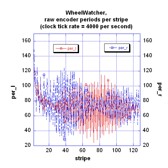
In the meantime, I tracked down at least one source of my problems in trying to “tune” a PID loop for my current project. This is a line maze solver based on the Solarbotics Sumovore outfitted with GM2 motors (slower than GM8) and the WheelWatcher modules. I could not find an appropriate Kd, but the reason is obvious when you look at the raw signals coming from the WheelWatcher modules.

Below, I plot the unfiltered “period per stripe” in ticks of 1/4000 second, for each of the 128 stripes per wheel revolution for the right and left wheels. The wheels were rotating at about 25 rpm.

The graph is horrifyingly noisy, which explains why the Nubotics folks found it necessary to use a low pass filter in front of the PID loop in the example posted on their site. With input data this noisy, it is hopeless to try to tune a loop. Unfortunately, the slow response of the filter makes it very difficult to find appropriate tuning parameters.

It seems possible that some of this noise is due to using “coast” mode PWM, perhaps from the gears. More later.

BTW I’ve posted a test program that allows one to enter motor control parameters via the rs232 serial line (USB adapter) with a terminal program, and to dump the results for plotting. It can be downloaded from

uoxray.uoregon.edu/orangutan/test_pwm.c

You’ll also need uart_mega8.c (for the atmega8 on the Sumovore). Onward and upward!

Jim

Cool! I haven’t had a chance to work on my line follower this week because of time constraints at work, but I’m hoping to get back at it this coming weekend. I’ll give your PID software a go. That’d be way nicer than having to re-flash it each time.

Tom