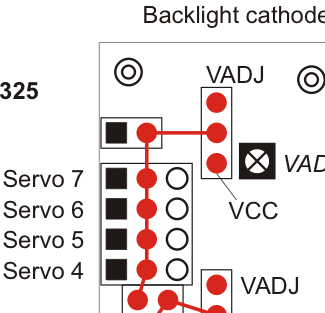
i want to use the VADJ-Output for swathing a magnet valve. i want to do it without an external relais, so i wondered if it is possible to do it via the servo pins on “Servo7” (see the screenshot). i turned the trimpot to max., jumpered for “VADJ”. but now? can you give me a sample code for this?
or is it possible to do this task via the normal I/O pins?
I’m not sure about how to wire the i/O pins to get a high voltage output.
what i did just now: VADJ-trimpot to max, on cable into the I/O-pin of D1, the other to the + pin of VADJ, executing the following code:
what my multimeter says is swathing between 5 an 10,7 V.
But what i need is a switch between 0 and 10,7 V.
So how could i reach that? What does the following instruction mean:
“You can cut a trace on the bottom of the board to disconnect them from VCC. This will leave the power pins connected to one through-hole, which can be connected to a different power source, such as VADJ, which is available elsewhere on the board.”
perhaps my english is not good enough to understand this, but I cannot see any connection between the two through-holes that i could cut. And if so, would that be the solution for what i am looking for?
I don’t understand what you mean by the “+ pin of VADJ”. If you connected PD1 to VADJ, that would almost certainly cause a short circuit that could permanently damage your SVP.
If you want an output that switches between 0 and 10.7 V, you should probably connect VADJ to a MOSFET. You should make sure that you aren’t drawing too much current from VADJ. I don’t know what a magnet valve is, but you should take any other precautions that might be necessary when controlling a magnet valve, e.g. you will probably need a flyback diode.
Maybe it would be possible for you to use the Orangutan SVP’s motor outputs instead.
I don’t know specifically which pins you are asking about, but some certain pins on the SVP can be disconnected from eachother. These pins are marked on the Orangutan SVP Reference Diagram with the “Jumper with cuttable connection on PCB bottom” symbol. If you look on the bottom of the PCB, you will see a line (trace) between the pins. This trace can be cut to sever the two pins.
ok, on the first picture you can see how my connection looks like:
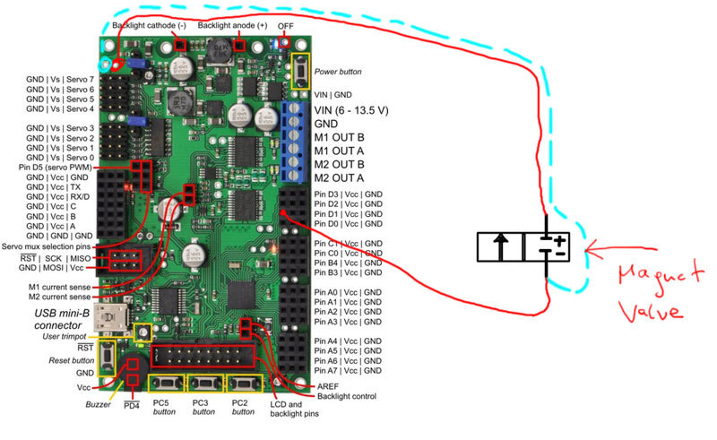
the two red wires are what i tried to describe in my last post. when i try the light blue wire instead of the red one on the - pole, i can switch my valve perfectly, but then i am directly on the VADJ, and i can only switch it by manually making a connection, but not controlled via the orangutan. the valve is closed without power and its 12V DC 7,58W, that must be about 630 mA,am i right?
ok, perhaps i’m a little bit naive… what is a flyback diode for? my magnet valve is opened with power and closed without, it works fine as long as i switch it manually. so i think my problem is not the valve itself but only finding a possibility to control a switch of the VADJ via one of the I/O-ports or the servo ports. is this possible? i can’t use the motor port, because both are used.
i think you are talking about the pins i marked light blue on my second picture. but i cannot see any trace between the two holes. what am i misunderstanding?
I don’t know anything about magnet valves but I think that’s correct. Any device with two terminals that consumes 7.58 W when 12 V is applied to it would be drawing about 630 mA of current.
In the red wire configuration, what you have done is connected PD1 to the negative terminal of your magnet valve device, and connected the other terminal to VADJ. This is not OK because pin PD1 can only sink a few tens of milliamps; it can NOT sink 630 mA.
So if i understood you right, it is NOT possible to get a swiched power like i need it for my described valve without aditional hardware like a mofset or a relais?
And cutting the trace between the holes only makes the power-pins higher voltage, but still not switchable, because the I/O - pin stays low mAmperes?
thank you. can i ask you to explain again, what exactly the flyback diode is for? does it protect the orangutan circuits or my magnet valve? is it just a general precaution procedure when using a divide with a coil to prevent an electric “shock”?
could you tell me which diode should look for that fits for my setting? ( i posted the values of the magnet valve. its just a simple coil that produces the magnetism for opening the valve with no additional electronics, 12V 630mA). if you want me to look for it by my own i would appreciate a link where different diodes are compared so that i can find one more easily, because for me as a complete electronics newbie its not easy to compare them.
the same thing with the mosfet: can you also tell me which one would be the right for me? i need to switch my valve (closed without power) for 2 short pulses (off->on for 200ms->off for 200ms->on again for 200ms → off). how do i connect a mofset correctly on the orangutan power pins and I/O-pin? i do not want to destroy anything. i thought a mofset can switch when i connect its third pin to the power pin (or the n-pin, depending on the mosfet-type). but how can i connect the mofset that its switched on/off by the SVP’s I/O-signal?
(i know i’m outing myself as a complete fool, but beleve me- i’m learning a lot here, and i think i’m learning faster this way than by reading lots of articles about microelectronics…)
Obviously, an expert personally guiding you should be better than just learning on your own, but be careful not to be lazy or greedy about it since you shouldn’t expect people to help you for free if you are not putting in the effort yourself. People devote their lives to teaching this stuff, and reading their articles and books is how you learn it. Yes, that does take a while.
If you have any questions about how the Orangutan SVP’s digital outputs behave, I’d be happy to answer them, but I can’t teach you basic electronics and how to design the circuit that will be controlled by the digital output. Since your questions are about electronics in general, and not specific to any Pololu product, it would be more appropriate to ask questions along those lines in the electronics general discussion section of our forum.