Orangutan/LSM303DLHC I2C Fails

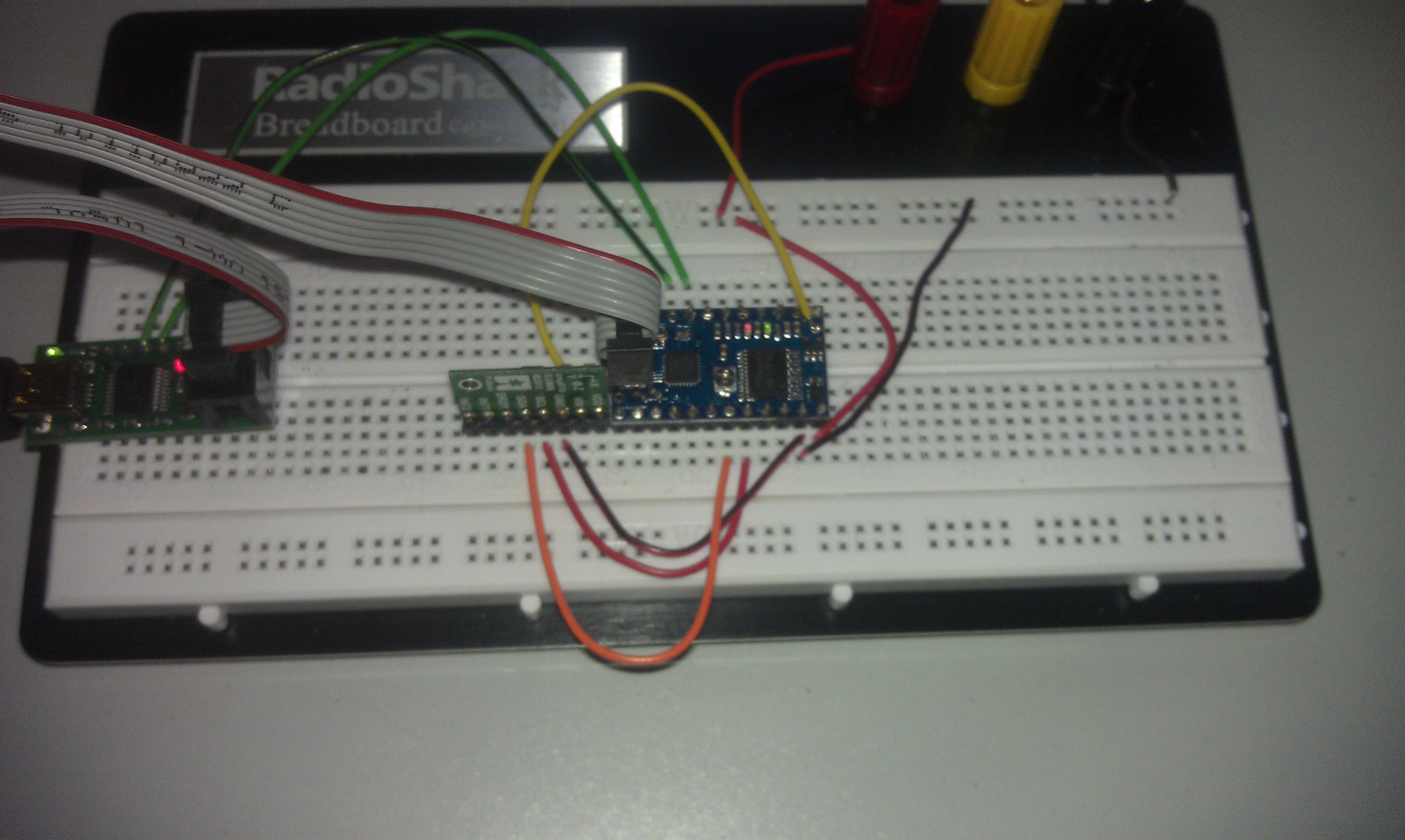
I have a Baby O: B-328 (https://www.pololu.com/catalog/product/1220) and LSM303DLHC (https://www.pololu.com/catalog/product/2124) connected to a breadboard.

B-328
11.5 volts to VIN from 8 AA batteries
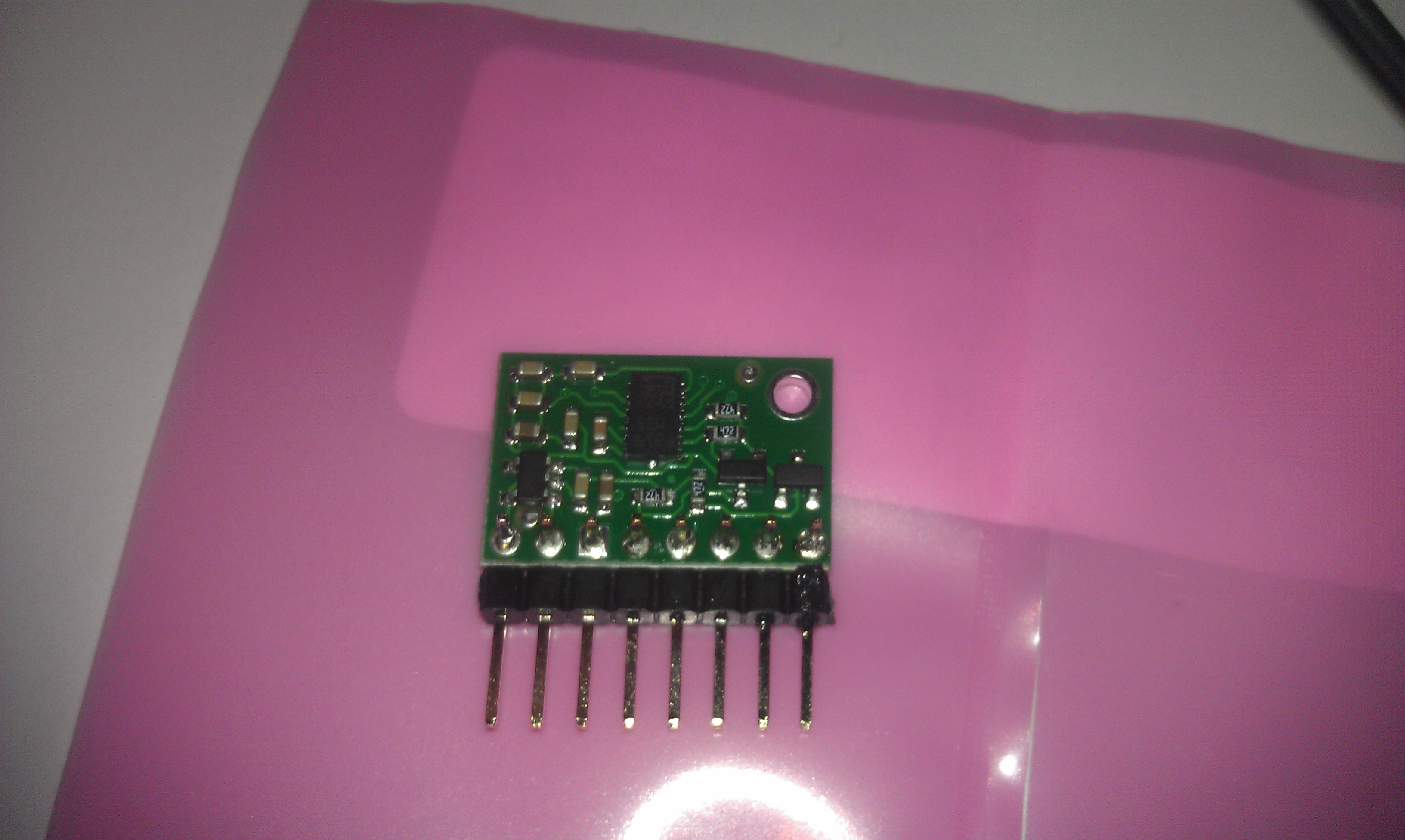
LSM303DLHC
4.98 volts from B-328 VCC

<Edit 12/30/2012 15:42 eastern>
(I made a mistake in explaining the first time)

LSM303DLHC SLC jumpered to B-328 PC4
LSM303DLHC SDA jumpered to B-328 PC5

Pins are actually:
LSM303DLHC SDA jumpered to B-328 PC4
LSM303DLHC SCL jumpered to B-328 PC5

While attempting to read from the CTRL_REG1_A (20h) Register of the LSM303DLHC’s Linear Acceleration Digital Interface (33h). It gets to the point after the i2c_start_wait(), lights the red LED and stops. I have tried other registers in the Linear Acceleration Digital Interface as well as trying the Magnetic Field Digital Interface (3Dh) and a couple of it’s registers and have the same results.

Pull-up resistors are on the board for the I2C, correct? So I don’t need external resistors. The LSM303DLHC’s on-board resistors measure 4.67k each.

To test PC4 and PC5
I have set PC4 and PC5 HIGH to light a LED each.
I also set PC4 and PC5 LOW. PC0 and PC1 HIGH. With a jumper PC0 to PC4 and PC1 to PC5 to check for proper input readings and they appear to be in good order.

Even if I comment out the red_led()s and delays prior to “i2c_write(0x20)” (Figuring the delays might impact the I2C process) and setting the following red_led(1) and a delay_ms(2000), the led does not light. I think it’s a “i2c_write(0x20)”, but what?

Any suggestion where to look next would be great.

#include <pololu/orangutan.h>
#include <i2cmaster/i2cmaster.c>
#include <i2cmaster.h>

#define F_CPU 20000000UL
#define LSM303DLC_ACCELERATOR  0x33      // device address

int main(void)
{
	unsigned char ret;
	
	red_led(1);
	delay_ms(100);

	i2c_init();                             // initialize I2C library
	
	red_led(0);
	delay_ms(100);

	// read previously written value back from address

	// set device address and write mode
	i2c_start_wait(LSM303DLC_ACCELERATOR+I2C_WRITE);
	
	red_led(1);
	delay_ms(100);

	i2c_write(0x20);                        // write address
	
	red_led(0);
	delay_ms(100);

	// set device address and read mode
	i2c_rep_start(LSM303DLC_ACCELERATOR+I2C_READ);
	
	red_led(1);
	delay_ms(100);

	ret = i2c_readNak();                    // read one byte
	
	red_led(0);
	delay_ms(100);

	i2c_stop();

	while(1){
		red_led(1);
		delay_ms(400);
		red_led(0);
		delay_ms(400);
	}
}

Hello.

To connect I2C devices, you actually need to connect SCL to SCL and SDA to SDA. You have it flipped. The correct I/O wiring would be:

LSM303DLHC SCL to ATmega328 PC5
LSM303DLHC SDA to ATmega328 PC4

Also, for completeness, you will need to connect the GNDs together and to supply power to the compass’s VIN pin.

I have not looked carefully at your code yet, but hopefully that will fix the problem.

I did notice that your main function returns; this can result in undefined behavior in avr-gcc so I recommend adding an infinite loop ( “while(1);” ) to the end of your program.

–David

To connect I2C devices, you actually need to connect SCL to SCL and SDA to SDA. You have it flipped. The correct I/O wiring would be:

LSM303DLHC SCL to ATmega328 PC5
LSM303DLHC SDA to ATmega328 PC4

I made a mistake in explaining the SLC and SDA connections in my post. They are as you said they should be.

Also, for completeness, you will need to connect the GNDs together and to supply power to the compass’s VIN pin.

The grounds are from the same bus on the breadboard. But I will connect them more directly…even move the LSM303DLHC closer to the B-328. The LSM303DLHC is powered to the VIN from VCC on the B-328 at 4.98 volts.

I did notice that your main function returns; this can result in undefined behavior in avr-gcc so I recommend adding an infinite loop ( “while(1);” ) to the end of your program.

Thank you for noticing, but I omitted the loop for brevitys’ sake. I have appended a “While” loop to my code.


After rechecking all of the connection and voltages, I have since retried the I2C connection with the same results. Perhaps I have damaged the LSM303DLHC. Is there any way of determining if there has been damage of the LSM303DLHC?

Hello.

Unfortunately, I think the only way you can really tell if the chip is working is to try talking to it over I2C with a microcontroller.

Could you please tell me where you got i2cmaster.h and i2cmaster.c from?

I have started comparing your code to our LSM303 Arduino library, which can be found at:
github.com/pololu/LSM303/blob/m … LSM303.cpp

One thing I noticed is that the proper I2C address to use is:

which probably doesn’t match the value of 0x33 you are using. Dealing with I2C addresses is tricky because there are multiple different conventions for representing the address as an integer which vary by a factor of two. Could you please try each of the following values for LSM303DLC_ACCELERATOR and see if that fixes the problem?

0x32
0x64
0x19

–David

I downloaded the i2cmaster.zip from http://jump.to/fleury/

Thank you for that code location.

I acquired the Linear acceleration digital interface address (0x33h[read] and 0x32h [write]) from the LSM303DLHC datasheet (https://www.pololu.com/file/download/LSM303DLHC.pdf?file_id=0J564)(page 20), and the CTRL_REG1_A address (0x20h) on page 24.

I did try the addresses as you suggested and had the same results or less. It would not progress any further than I had when I had started.

Could you provide some pictures of your setup so we can check all the connections and solder joints? You can use the “Upload Attachment” tab when you are writing your reply.

–Davd

Thank you for taking a look at it. Maybe I missed something.

When the power is off to the Baby O, are the red and green LEDs suppose to be dimly lit with the Tx and Rx connected for serial connection through the USB Programmer?


Thanks for the pictures. I don’t see anything particularly wrong with your connections. However, I can’t really see the solder joints on the LSM303DLHC carrier.

I found a Baby Orangutan B-328 and a LSM303DLHC (cmp01b) here and I was able to get basic I2C communication working. My code successfully reads CTRL_REG1_A and verifies that the value is 7, which is the default. Here is the working code:

#include <pololu/orangutan.h>
#include "i2cmaster.h"

#define ACC_ADDRESS_SA0_A_HIGH  0x32

int main(void)
{
	i2c_init();
	delay_ms(10);

	// Read the value of CTRL_REG1_A, which should be 7 (0b111) by default.
	i2c_start_wait(ACC_ADDRESS_SA0_A_HIGH + I2C_WRITE);
	i2c_write(0x20);
	i2c_rep_start(ACC_ADDRESS_SA0_A_HIGH + I2C_READ);
	uint8_t reg = i2c_readNak();
	i2c_stop();
	
	while(1)
	{
		red_led(1);
		delay_ms(200);
		red_led(0);
		delay_ms(200);
		if (reg == 0b111)
		{
			delay_ms(800);
		}
	}
}

I have attached my entire Atmel Studio solution below as a zip file. It includes the HEX file that worked for me, named “worked_for_david.hex”. In order to eliminate any possibility of compilation errors, could you try loading that HEX file onto your Baby Orangutan without modifying it? If it works, you should see the red LED blink every 1.2s. Faster blinking would mean that it received the wrong value from I2C.

babyo_lsm303dlhc.zip (6.8 KB)

The only meaningful change I really made to your code is changing the address to 0x32. It wouldn’t make sense for the address to be odd like 0x33, because when you add I2C_READ (1) to it you would be modifying two bits, but you only need to modify one bit to switch between writing and reading.

The I2C library uses the F_CPU directive, so you should be sure to use the -DF_CPU=20000000 compiler option, because the Baby Orangutan is running at 20 MHz.

When I downloaded homepage.hispeed.ch/peterfleury/i2cmaster.zip , the only .c file I got was named twimaster.c. Did you choose to rename it to i2cmaster.c, or did you perhaps download it from somewhere else?

If you continue to have trouble, please check all the connections to the IMU with multimeter. You should check that the proper votlage is being delivered to VIN, and while your system is powered off check for continuity. Make sure to probe at appropriate points on the boards so that you can be sure that your solder joints, wires, and breadboard are making the connections we expect them to be making. A picture of the LSM303’s solder joints might be helpful.

–David

You are very welcome. And thank you for spending the time to help. The solder joints on the LSM303DLHC carrier look better than on the Baby O. (With the exception of VDD on the carrier. It will not be used.

I tried your “worked_for_david.hex” and it still did not work. I am believing I have damaged the sensor since everything else I have tried on the Baby O has worked as it should and your code worked with your assembly.

I showed the 0x33 address because it was the address that went further through the code than any other had.

The I2C library uses the F_CPU directive, so you should be sure to use the -DF_CPU=20000000 compiler option, because the Baby Orangutan is running at 20 MHz.

I went back into the i2cmaster library to look at what I had in there and see more than I had remembered. So, I downloaded the homepage.hispeed.ch/peterfleury/i2cmaster.zip and it didn’t look like what I had, but I did have all of the files in the i2cmaster.zip, and some others. There was a i2cmaster.c in the library as well as the i2cmaster.c. They were both identical but I do not believe I would copy and change the name of the file. I do not know that much about this programming to try that. I would upload a zip of my i2cmaster library for you to see what is there, but I don’t want my library to be floating around…if it is not a valid library. I don’t know where the other files came from. I have been very tired while working on this project and cannot say what I have and have not done at times.

I have uploaded the picture of the LSM303’s solder joints.

Thank you again for your help. I have a new LSM303DLHC carrier coming in the next couple days. I will clean out all libraries, put in fresh libraries and start anew. Look for post from me after the new sensor arrives.

Tony


David, I received my new LSM303DLHC today, and the files as you offered worked as soon as I assembled the device and applied power.

I must have had some ESD while I was assembling the breadboarded unit. I am sure I will be back to this forum while attempting to complete my task for this device…and others! Thank you!

i2cmaster.h sounds very similar to something pulled from the Ic2 dev libary. Maybe your library happens to have the same name, or maybe it is the same.

But the library is not automatically compatible with 20mhz. It should be, but there’s a mistake somewhere where they use 16mhz instead of F_CPU, so it doesn’t compile with knowledge that the baby orangutan runs at 20mhz, not arduino’s 16mhz.

When I was working with the MPU6050 on the i2cdev libary, I summarized my findings as this:

It sounds like you have some other ideas as to what might be the problem…but since I couldn’t check in your ic2master file (the link wouldn’t load for me) I am going to throw the information out for you to investigate if you deal applicable.