I’m making a line follower , and I use 4 engines pololu 30:1 , I will use 2 on each side of MATCHED . I have a Shield to control the motors based on L298N chip .
My question is this , I bought one pair of optical encoders pololu as robocore not found in the store , I’ll put the direct link pololu - > pololu.com/product/2590 .
Hence my doubt arose in this specification encoder , ( I already have here) , says he operates with a voltage up to 5V , however , I will use an external battery to power the motor which is a 2-cell 1350mAh LiPo , and tension it is 7.4V and another battery for the arduino .
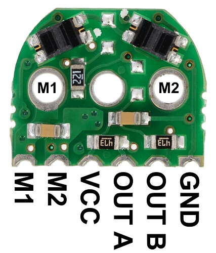
These encoders go straight pins motor power , as shown in this photo pololu.com/picture/view/0J4763 , motors operate at 9V and 6 , how to proceed in this case , since the encoders are direct soldiers on the engine ?
My question is the following , these encoders can burn the battery voltage with the engine or they have an internal resistor for this? or else they have pinout to connect the encoder motors separately , ie , the power of the engines go to the entrance of the engines in the Shield and encoder , 5V on the arduino ?
Sorry for english.

