Just got my Orangutan X2 board. Compiling the test code etc and everything works great.
But the doc is lacking in explaining where and how to plug up the analog in sources.
Took me a while to figure out that you need to connect ex: positive to ad4 and negative to ad4(-)
I was connecting ad4 with minus and ad4(+) with positive (wrong). Well I think.
Is there more detailed doc on pinouts and which are available for Analog in :
Which 8 ???
Am I doing this correctly…
Thanks a buch
Chris
As an initial word of caution, if you don’t understand how to connect something, you should definitely be asking for help before you actually try to make your connections. Connecting things incorrectly could permanently disable the controller, so you don’t want to be operating with the attitude of “let’s try this and hope it works”.
The analog inputs on the X2 are pins PA0 - PA7. This is covered in the datasheet for the X2’s ATmega644 microcontroller, which is linked from the resources tab of the X2 product page. We will be adding support for the Orangutan X2 to the Pololu AVR library in the coming months, but for now the MCU’s datasheet, our sample X2 code, and this forum are probably your best resources when it comes to programming the X2.
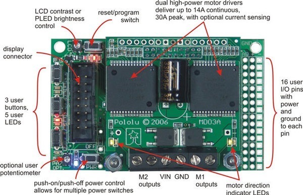
As far as how to connect an analog source to the Orangutan X2, this will depend on what you are connecting. At a minimum, you will want to connect your analog voltage to one of the mega644’s analog inputs, and you need to make sure that your analog source and the Orangutan X2 share a common ground. Note that pins PA6 and PA7 are connected to the system voltage monitor circuit and the user trimpot, respectively, by default (through SMT jumpers on the underside of the board), so I recommend you select a pin from PA0 - PA5. The pins in the interior column of the 3x16 female header (the left column in the labeled picture you posted) connect directly to the microcontroller I/O lines. The pins in the middle column connect to the board’s power bus (by default this is the output of the 5V regulator). The pins in the exterior column all connect to ground.
If your analog source is a sensor that requires power, you will want to connect its power to a pin in the middle (+) column and ground to a pin in the exterior (-) column. You will the connect its output to an interior column pin that is in the PA0 - PA5 row. If your analog source gets its power another way, you only need to connect signal and ground. If you’re connecting a potentiometer, you want to connect one side to 5V and the other to ground; the output of the wiper (typically the middle pin) goes to signal.
Does this make sense? What specifically are you trying to connect?
This is a related question. For the power on the ADC, is there a current limit on the power ports? Or, what can each port drive? Is there a total power that must not be exceeded? Are there any similar current limits on the ADC ports themselves? Are there standard fuse strategies that people use if they are not sure about the currents or is it just easier to buffer (op amp type circuit)?
I did look at that and figured out that the PA0 - PA7 where the analog in’s it just was not clear to which column and how I should connect physically. But you explained that perfectly, thanks. Now that I think of it, it all makes perfect sense. I guess it was getting too late for me to think straight.
I was performing tests with a low voltage source (1.5v), but I agree trial and error is bad.
So shame on me!
I am connecting a temperature sensor and a CO2 sensor for a project and got those working. Next step is controlling the temp and CO2 levels.
I’m glad to hear that you have made progress. I wasn’t referring to the Orangutan X2 schematic, I was referring to the ATmega644 datasheet, which you can find on atmel’s website: