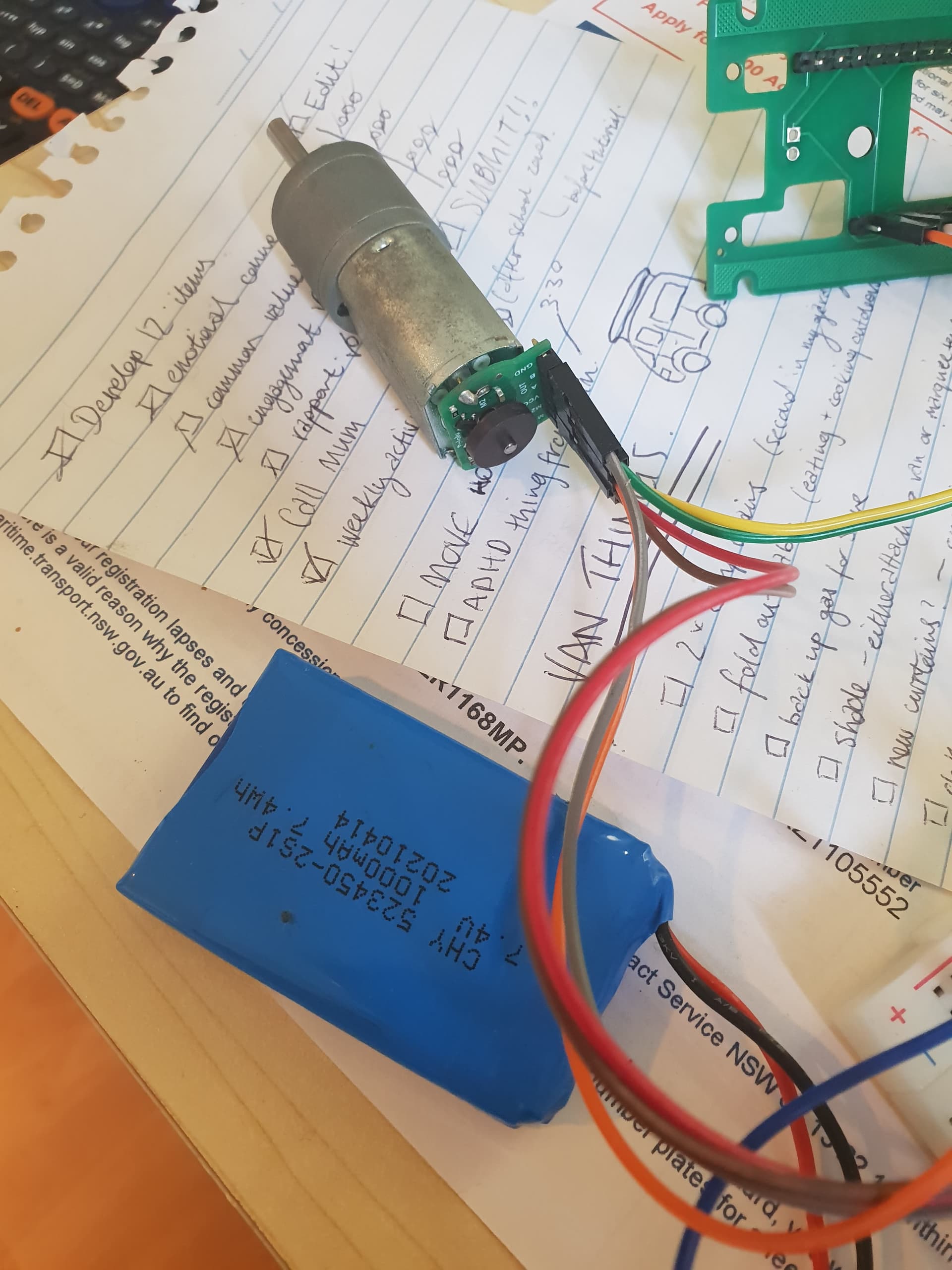
I have my entire project working. I have my motor being controlled with a DRV8835 controller with encoder feedback and everything else working. But I am unable to get current feedback with this current sensor (https://www.pololu.com/product/2452) . As far as I am aware I have everything connected correctly (please see images below) and still have the motor working even though the power source is connected through the current sensor. It just seems the value I am reading with an analog pin doesn’t change even when I am putting more load on the motor (with my hand).
I am struggling to understand exactly how to code this and get it working. I have set up the formula and wrote a function below according to the formula on the pololu website but it only outputs 0 regardless of if the motor is on or off. When I read the raw value from the Vout pin it doesn’t vary and floats between (790 and 810) even when I am stalling the motor.
float printCurrentValue(int value) {
  float current = 36.7 * (value/5) - 18.3;

}
Hello.
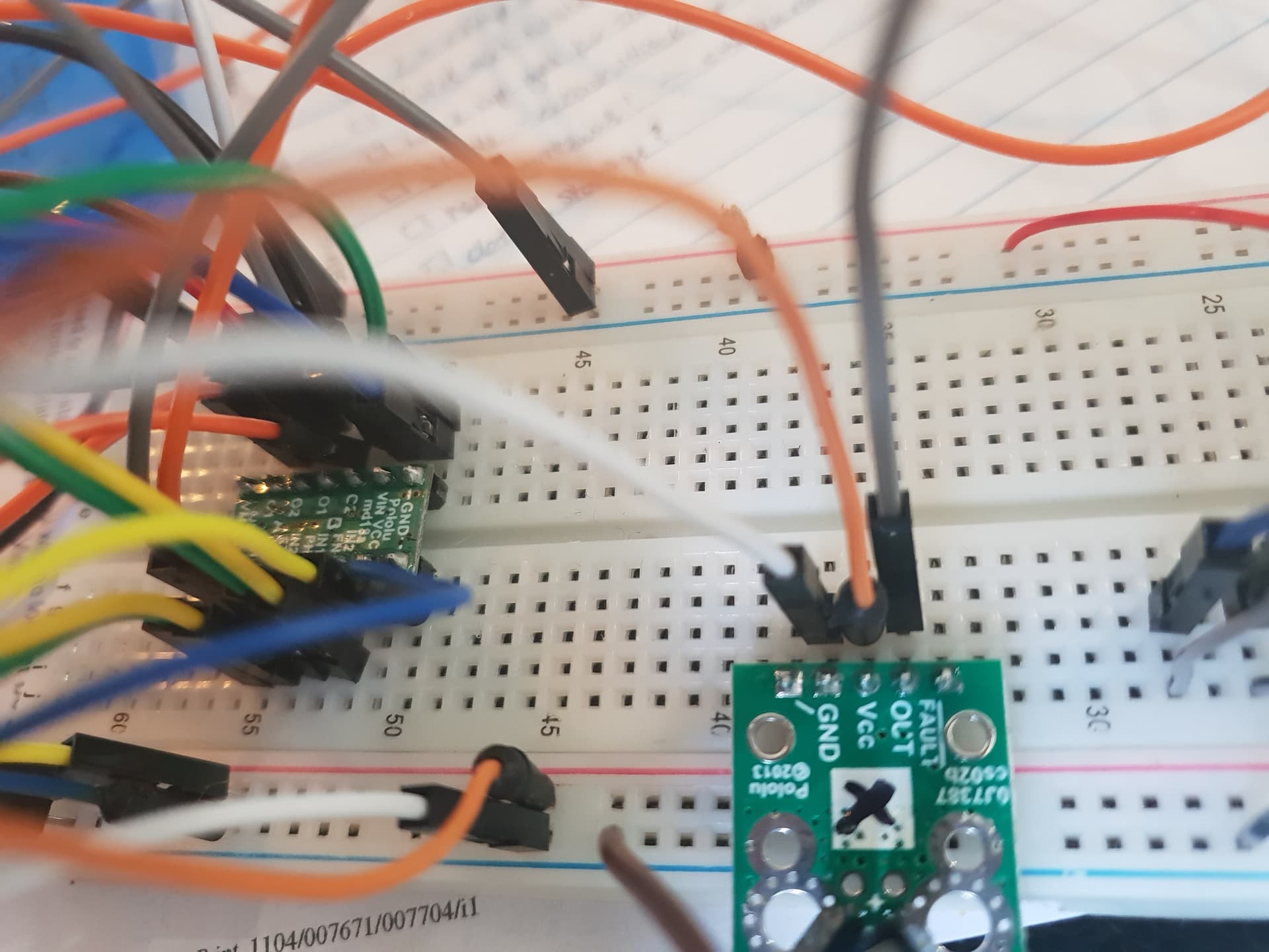
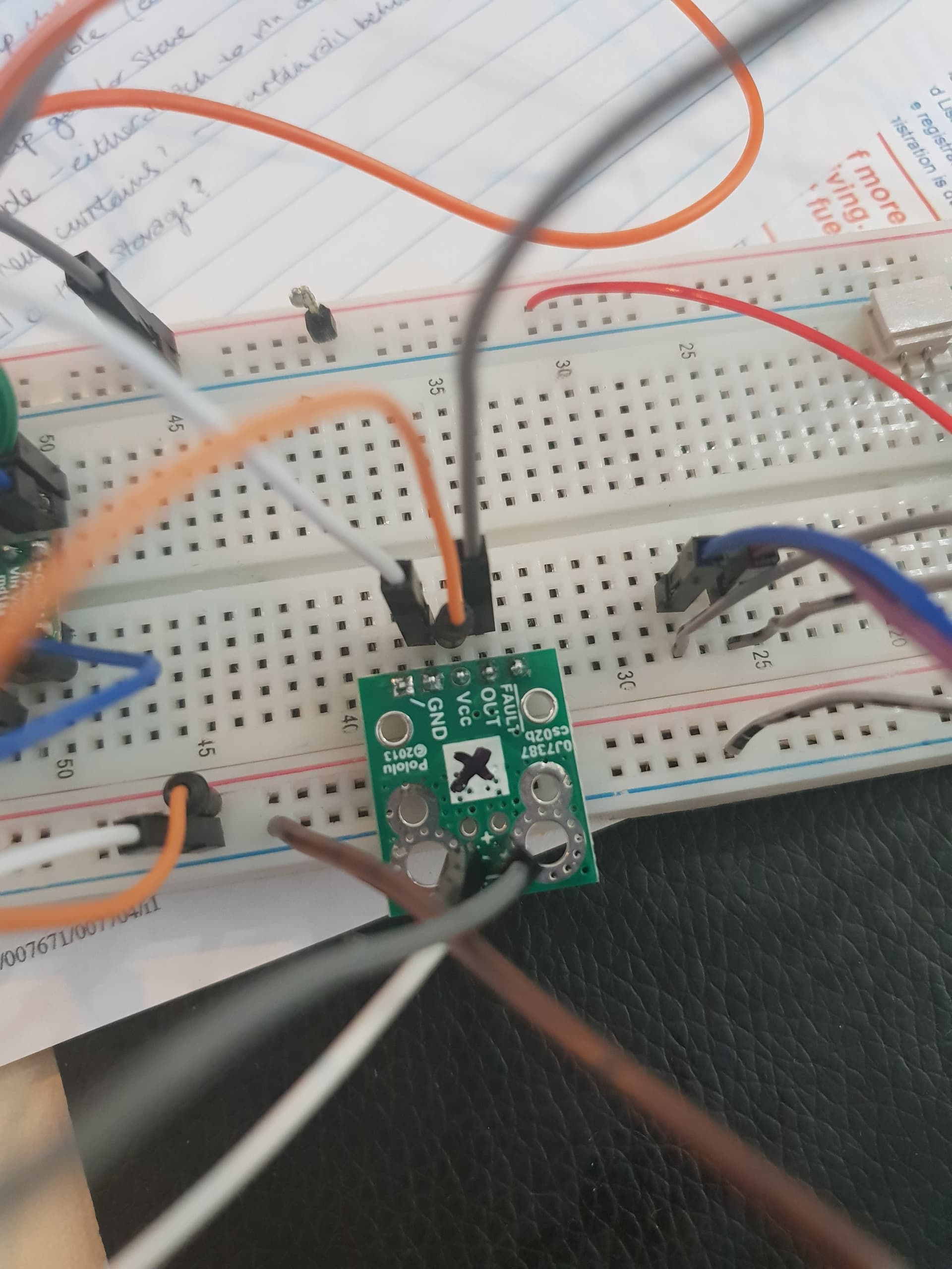
It is hard to see how everything is connected in your pictures. Can you post a schematic for your setup that shows all of the connections, or a clear overhead picture of the full system with the wires organized as neatly as possible? What microcontroller are you using to monitor the current sensor’s OUT pin?
Can you also confirm that your connections to the IP+ and IP- pins (the pins you are measuring the current through) are soldered?
By the way, the function you posted looks like it might be incomplete (maybe you intended to include a line to actually print or return the value too?). However, I think we should just focus on getting decent raw analog readings first, so I would recommend testing your setup with the simplest possible program that demonstrates the problem. For example, one that just powers the motor and reports the analog readings from the current sensor’s OUT pin directly.
- Patrick
I also think it will be more helpful if you please share a schematic or connection chart. And I request pololu to add a small and simple sample code for this product. So that users like us can understand whether they’re going to the right direction.
Our current sensors output an analog votlage that is linearly proportional to the input current, so the code for obtaining a raw value would just be to perform an analog read. There is an Arduino example for that here.
If you need to convert the raw value into units of amps for your application, that will depend on the voltage you are applying to the sensor’s VCC pin, the precision of your controller’s analog-to-digital-converter (ADC), and the specific sensor you are using.
- Patrick
Thanks a lot Mr. PatrickM. Very much appreciated.
Hey Patrick, thanks for getting back to me. I am using an A-star board which works fine for everything except this module (I’ve tried a couple).
When I am reading the raw analog input from the current sensor it reads about 800-810, and when I turn the motor on it doesn’t vary, when I load the motor it again doesn’t vary. I am just reading the analog input from the sensor and it doesn’t seem to be working. I have not soldered it as I just have header pins on it, but assumed that would be fine since the motor is still running (thus connection is good).
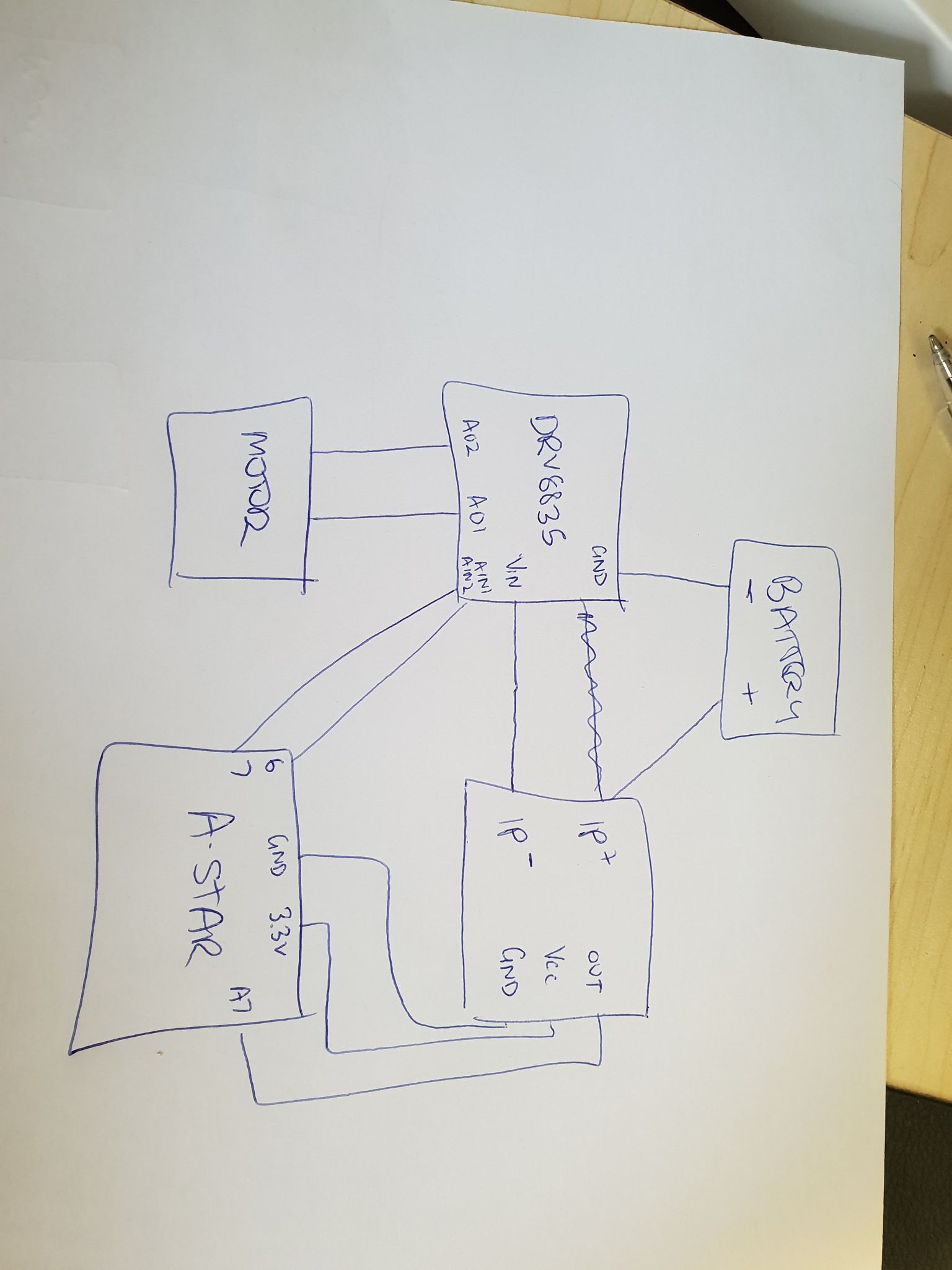
Thanks for suggesting this code, I have tried using it already and got the result in the above reply. But I just completed a wiring diagram and am hoping that is is wired up correctly!
Even if your devices still appear to be getting powered properly, unsoldered connections still might be intermittent and cause problems like voltage spikes. Can you try soldering all of the pins you are using and let us know if that changes your results?
Also, we offer several different A-Star controllers; can specify which particular one you are using? Unless you are using one of our A-Star 328PB Micro boards that are configured for 3.3V operation, I would recommend connecting your A-Star’s 5V output (instead of it’s 3.3V output) to the sensor’s VCC pin.
By the way, I expect this is just an error in your diagram since your driver is working, but the diagram does not show how the driver’s VCC pin is being supplied or a common GND between your driver and the A-Star.
- Patrick
Hey Patrick, I am using the A-Star 3.3V 8Mhz board. I have tried soldering all the pins and that was an error in my wiring diagram (sorry I just drew it up quickly). Can confirm that there is a common ground and everything else works.
I have just tried it again and this is the result: This is directly from reading the raw analog voltage and when I run the motor on the 5th line the value does change, but I would say not significantly as when I turn it off again teh value doesn’t change. I’m not sure what the next steps would be to fixing it.
|Position of motor: 0|encoder position: 0 - Current Value: 768|
|---|---|
|Position of motor: 0|encoder position: 0 - Current Value: 770|
|Position of motor: 0|encoder position: 0 - Current Value: 770|
|Position of motor: 0|encoder position: 0 - Current Value: 768|
|Position of motor: 0|encoder position: 0 - Current Value: 770|
|Position of motor: 0|encoder position: 0 - Current Value: 766|
|Position of motor: 0|encoder position: 0 - Current Value: 769|
|Position of motor: 0|encoder position: 0 - Current Value: 769|
|Position of motor: 0|encoder position: 0 - Current Value: 774|
|Position of motor: 0|encoder position: 0 - Current Value: 778|
|Position of motor: 0|encoder position: 0 - Current Value: 781|
Can you double check that you are powering the sensor with 3.3V and not 5V? Please also post the program that generated that output.
If you haven’t already, I would also recommend that you try monitoring your current sensor’s output using an oscilloscope.
- Patrick
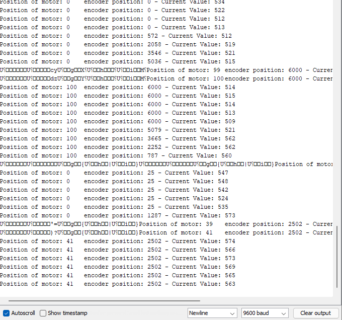
Hey, I can confirm it is being powered with 3.3V. Here is an image of the output and here is the code. I found when I started holding onto the motor it went from a raw value of about 510-530 to 560, but when going from off to on (without loading it) the value went from 510-530 to 540, but now I have stalled it and the motor is off the raw value is sitting at about 560-580. It seems to be inconsistent and I am not sure why.
void loop() {
  voc, humidity, temperature;
  uint8_t data[9], counter;

  unsigned long currentMillis = millis();

  if (currentMillis - previousMillis > interval) {
    previousMillis = currentMillis;

    // read measurement data
  Wire.beginTransmission(SVM40_ADDRESS);
  Wire.write(0x03);
  Wire.write(0xA6);
  Wire.endTransmission();

  // wait 5 ms to allow the sensor to fill the internal buffer
  delay(5);

  // read measurement data svm40, after two bytes a CRC follows
  Wire.requestFrom(SVM40_ADDRESS, 9);
  counter = 0;
  while (Wire.available()) {
    data[counter++] = Wire.read();
  }

  // VOC level is a signed int and scaled by a factor of 10 and needs to be divided by 10
  // humidity is a signed int and scaled by 100 and need to be divided by 100
  // temperature is a signed int and scaled by 200 and need to be divided by 200
  voc = ((uint16_t)data[0] << 8 | data[1])/10;
  humidity = ((uint16_t)data[3] << 8 | data[4])/100;
  temperature = ((uint16_t)data[6] << 8 | data[7])/200;

/*  temp_graph = temperature / 200;
  humidity_graph = humidity / 100;
  voc_graph = voc / 10; */

  Serial.print("Position of motor: ");
  Serial.print(position_setting);
  Serial.print("\t");
  Serial.print("encoder position: ");
  Serial.print(encValue);
  /*Serial.print("\t");
  Serial.print("MAX VALUE: ");
  Serial.print(MAX_ENC_COUNT);
  Serial.print(" - voc: ");
  Serial.print(String(voc));
  Serial.print("\t");
  Serial.print("Humidity(%): ");
  Serial.print(String(humidity));
  Serial.print("\t");
  Serial.print("temp: ");
  Serial.print(String(temperature));
  Serial.println();*/
  Serial.print(" - Current Value: ");
  Serial.println(analogRead(A7));


  }
}
It seems like we are starting to make some progress. I am not sure what caused this change, but if your readings when the motor is not running are now close to 512, that is around what we would expect since the sensor outputs a proportional analog voltage centered at Vcc/2 and analogRead on the A-Star 328PB reports analog measurements with integers between 0 and 1023.
It is still not clear whether or not the range of values you are seeing makes sense. Can you let us know what specific motor and battery you are using? Also, the program you posted seems to include code for several unrelated tasks, and I do not see how it is driving your motor. Can you write a simple program like I suggested earlier, one that just reports current sensor readings while toggling power to the motor? Please post the complete program for that along with what it outputs.
- Patrick
Hey Patrick, I have written a basic function that works and toggles the motor on and off but also outputs the current sense analog input.
The code is below as is the serial monitor output. There appears to be a slight difference in values from when the motor is on and off, however wouldn’t that account for much of a difference I would think. I also noticed as I ran the process a few times the values were rarely in the same range with an identical setup and code. But please see below:
void loop() {
  unsigned long currentMillis = millis();

  if(currentMillis - previousMillisRead > 250) {
    previousMillisRead = currentMillis;
    Serial.print(" - Current Value: ");
    Serial.println(analogRead(A6));

  }

  if(currentMillis - previousMillisGo > 2000) {
    previousMillisGo = currentMillis;
    swap = !swap;
    Serial.print("Changed mode here ");
    Serial.println(swap);
  }

  if (swap) {
    digitalWrite(m_phase, HIGH);
    digitalWrite(m_enable, LOW);

  }
  if (!swap) {
    digitalWrite(m_phase, LOW);
    digitalWrite(m_enable, LOW);
  }
}
First Serial Monitor Output:
Start Program...
Setup complete...
 - Current Value: 521
Changed mode here 1
 - Current Value: 525
 - Current Value: 529
 - Current Value: 526
 - Current Value: 527
 - Current Value: 520
 - Current Value: 526
 - Current Value: 526
Changed mode here 0
 - Current Value: 521
 - Current Value: 521
 - Current Value: 521
 - Current Value: 521
 - Current Value: 521
 - Current Value: 521
 - Current Value: 521
 - Current Value: 519
Changed mode here 1
 - Current Value: 531
 - Current Value: 527
 - Current Value: 526
 - Current Value: 525
 - Current Value: 527
 - Current Value: 528
 - Current Value: 526
 - Current Value: 525
Changed mode here 0
 - Current Value: 521
 - Current Value: 521
 - Current Value: 520
 - Current Value: 520
 - Current Value: 522
 - Current Value: 522
 - Current Value: 520
 - Current Value: 521
Changed mode here 1
 - Current Value: 529
 - Current Value: 525
 - Current Value: 525
 - Current Value: 525
 - Current Value: 527
 - Current Value: 527
 - Current Value: 526
 - Current Value: 526
Changed mode here 0
 - Current Value: 521
 - Current Value: 520
 - Current Value: 522
 - Current Value: 521
 - Current Value: 521
 - Current Value: 520
 - Current Value: 520
 - Current Value: 521
Changed mode here 1
 - Current Value: 528
 - Current Value: 527
 - Current Value: 528
 - Current Value: 528
 - Current Value: 526
 - Current Value: 524
 - Current Value: 526
 - Current Value: 527
Changed mode here 0
 - Current Value: 520
 - Current Value: 522
 - Current Value: 520
 - Current Value: 521
 - Current Value: 521
 - Current Value: 520
 - Current Value: 521
 - Current Value: 521
Changed mode here 1
 - Current Value: 527
 - Current Value: 525
 - Current Value: 525
 - Current Value: 526
 - Current Value: 525
 - Current Value: 528
 - Current Value: 533
 - Current Value: 529
Changed mode here 0
 - Current Value: 524
 - Current Value: 523
 - Current Value: 522
 - Current Value: 522
 - Current Value: 522
Second Serial Monitor Output
Setup complete...
 - Current Value: 531
Changed mode here 1
 - Current Value: 536
 - Current Value: 538
 - Current Value: 536
 - Current Value: 536
 - Current Value: 539
 - Current Value: 538
 - Current Value: 538
Changed mode here 0
 - Current Value: 531
 - Current Value: 531
 - Current Value: 530
 - Current Value: 530
 - Current Value: 530
 - Current Value: 531
 - Current Value: 530
 - Current Value: 531
Changed mode here 1
 - Current Value: 544
 - Current Value: 537
 - Current Value: 538
 - Current Value: 535
 - Current Value: 536
 - Current Value: 535
 - Current Value: 537
 - Current Value: 536
Changed mode here 0
 - Current Value: 532
 - Current Value: 531
 - Current Value: 531
 - Current Value: 531
 - Current Value: 532
 - Current Value: 532
 - Current Value: 533
 - Current Value: 530
It appears to be different, but with each attempt at it the values for the motor being on and motor being off appear to be different each time.
What specific motor and battery you are using, and can you make sure your battery is charged? Please also try manually monitoring your current sensor’s OUT pin with an oscilloscope to check if that matches what your A-Star is reporting. Does that result change if you add some extra load to the motor?
- Patrick