
We are experiencing non-deterministic behavior from our custom 20-sensor array built from Pololu QTRXL-MD-01RC reflectance sensors. Specifically, calibration is coming back differently after each power cycle to the array. What would explain this?

Hello.
Can you tell me more specifically about what is going on and how you are using those sensors? How are you supplying power? What are you using to read the sensors? What code are you running? Can you post a sample of the values you are getting that show the behavior you are noticing?
-Jon
The array is connected to an Arduino Mega. 5V power to the array is coming from a power regulator on the robot. The Arduino is powered via USB. The latter is alternately plugged into a laptop or an NI RoboRIO.
We need to save calibration values over the long haul (across power cycles, matches, etc.), so we’re writing them to the Arduino EEPROM. What we’re seeing is that if we power cycle the array (if the robot gets power cycled), then when we calibrate again, the values are dramatically different.
We speculate that we may have a grounding problem, since the laptop USB and the robot-powered array don’t share a common ground. We’re in the process of verifying that we see the same thing when connected to the RoboRIO (which does share a common ground with the array), but we aren’t there yet.
FWIW, we had this all working on the bench (with unshared grounds in that case as well).
Shouldn’t calibration values for individual sensors be fairly consistent through time (and across power cycles)?
Thanks,
Eric
I don’t have output handy, but here’s an example of our code that performs calibration and EEPROM storage. We’re hoping to use readLine to guide a PID controller to do basic robot centering (H-Drive) over a ~2-inch white line. We’ve had this working in concept, but the sudden non-determinism in calibration has us shook.
Basically:
- We calibrate
- Store values in EEPROM
- Power cycle the array
Upon re-calibration, we can see that the individual calibration values are very different from those we’ve stored in the EEPROM.
We’re using readLine, but averaging the last 10 values to try to get a more stable value to aim our PID controller.
I should add that we’ve fixed QTRSensors.cpp so that it will allow a 20-sensor array (it was hard-coded to limit calibration to 16 sensors).
#include <QTRSensors.h>
#include <EEPROM.h>

#define TIMEOUT 2500
#define EMITTER_PIN 53
#define NUM_SENSORS 20
#define BUTTON 2
#define COUNTS_TO_AVERAGE 10


QTRDimmableRC array1((unsigned char[]){33,34,35,36,37,38,39,40,41,42,43,44,45,46,47,48,49,50,51,52},
  NUM_SENSORS, TIMEOUT, EMITTER_PIN);

unsigned int sensorValues[NUM_SENSORS] = {0};
unsigned int count = 0;
unsigned long avg = 0;
unsigned int storedVals[COUNTS_TO_AVERAGE] = {0};

void setup() {
  Serial.begin(9600);
// put your setup code here, to run once:
  pinMode(BUTTON, INPUT_PULLUP);
  array1.calibrate();
  updateCalibration();
}

void loop() {
  // put your main code here, to run repeatedly:

  if(count == COUNTS_TO_AVERAGE){
    for(int i = 0; i < COUNTS_TO_AVERAGE; i++){
      avg += storedVals[i];
    }//end for
    avg = avg/count;
    Serial.print(avg);
    Serial.print('\n');

    avg = 0;
    count = 0;


  }//end if

  storedVals[count] = array1.readLine(sensorValues, QTR_EMITTERS_ON, true);
  count++;
//  array1.readCalibrated(sensorValues);
//  for(int i = 0; i < NUM_SENSORS; i++){
//    Serial.print(sensorValues[i]);
//    Serial.print(' ');
//  }
//  Serial.print("\n");

  if(digitalRead(BUTTON) == LOW){
    //Print calibration arrays

    Serial.println("Old Calibration");
    for(int i = 0; i < NUM_SENSORS; i++){
        Serial.print(array1.calibratedMaximumOn[i]);
        Serial.print(' ');
      }//end for
      Serial.print('\n');
    for(int i = 0; i < NUM_SENSORS; i++){
        Serial.print(array1.calibratedMinimumOn[i]);
        Serial.print(' ');
      }//end for
    Serial.print('\n');

    array1.resetCalibration();

    Serial.println("Reset Calibration");
    for(int i = 0; i < NUM_SENSORS; i++){
      Serial.print(array1.calibratedMaximumOn[i]);
      Serial.print(' ');
    }//end for
    Serial.print('\n');
    for(int i = 0; i < NUM_SENSORS; i++){
      Serial.print(array1.calibratedMinimumOn[i]);
      Serial.print(' ');
    }//end for
    Serial.print('\n');

    while(digitalRead(BUTTON) == LOW){
      array1.calibrate();
    }// end while

    Serial.println("New Calibration");
    for(int i = 0; i < NUM_SENSORS; i++){
        Serial.print(array1.calibratedMaximumOn[i]);
        Serial.print(' ');
      }//end for
      Serial.print('\n');
      for(int i = 0; i < NUM_SENSORS; i++){
        Serial.print(array1.calibratedMinimumOn[i]);
        Serial.print(' ');
      }//end for
    Serial.print('\n');

    saveCalibration();
    Serial.print("\n\n");

    Serial.println("EEPROM contents");
    for(int i = 0; i < NUM_SENSORS * 4; i++){
      Serial.print(EEPROM[i]);
      Serial.print(' ');
    }//end for
    Serial.print("\n\n");

  }//end if


}
void saveCalibration(){
  for(int i = 0; i < NUM_SENSORS; i++){
    EEPROM.update(i*2, array1.calibratedMaximumOn[i] / 10);
    EEPROM.update((i*2)+1, array1.calibratedMaximumOn[i] % 10);
    EEPROM.update((i + NUM_SENSORS)*2, array1.calibratedMinimumOn[i] / 10);
    EEPROM.update((i+NUM_SENSORS)*2 + 1, array1.calibratedMinimumOn[i] % 10);
  } // end for loop
}//end saveCalibration

void updateCalibration(){

  for(int i = 0; i < NUM_SENSORS; i++){

    array1.calibratedMaximumOn[i] = EEPROM[i*2] * 10 + EEPROM[(i*2)+1];

    array1.calibratedMinimumOn[i] = EEPROM[(i + NUM_SENSORS)*2] * 10 + EEPROM[(i + NUM_SENSORS)*2 + 1];

  }//end save step

}//end updateCalibration
Here’s our basic setup (before mounting on the robot).
- 20 reflectance sensors wired through patch panel to Arduino Mega
- Sensors powered from separate 5V power source
- Arduino powered from laptop USB (on bench) and NI RoboRIO USB (on robot)
- Limit switch as calibration button (we want to be able to calibrate on demand, and save those values for multiple competition matches)
This all seemed to work OK on the bench, but since it’s been mounted to the robot, we’re seeing the non-determinism in calibration values upon power cycles… even just power cycles of the sensor array alone.
Nevermind. We fixed it!
It was indeed an odd problem with common grounding. We put a digital oscilloscope on the sensor leads and could see an odd signal messing with the emitter signal when the Arduino was plugged into the laptop. We had assumed that having the Arduino plugged into the RoboRIO’s USB would give them a common ground. That was incorrect. Explicitly connecting the Arduino to the same ground as the sensor array made the odd emitter signal go away.
The deformed emitter signal seemed to be seriously messing with calibration, making it highly non-deterministic.
1 Like
I am glad you were able to figure things out! Thanks for telling us what the issue was.
By the way, your application looks pretty interesting. What are you working on? If you have pictures, videos, or a write-up, we would love to see it! (Feel free to post links here or to the Share Your Projects part of our forum.)
-Jon
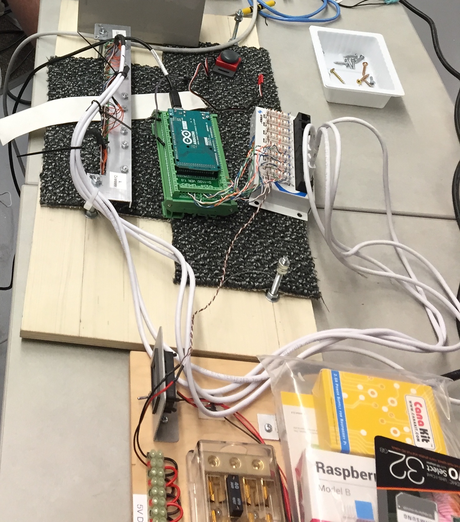
Thanks Jonathan. The application is automated centering on a goal for a FIRST Robotic Competition (FRC) robot. These are large powerful robots, so our efforts have been aimed at scaling the system. Basically we’re using the reflectance sensors to help us center over a white tape on a dark gray carpet as an autonomous driver aid. To do this we designed a 20-sensor array using QTRXL-MD-01RC sensors. We chose these for maximum range as we need the array to be about 2 inches off the floor.
All of the sensors run into an Arduino Mega. Our team designed a couple of 3D-printed carriages to hold the sensors at a couple of different pitches (the bright green bits). We arranged them for higher density in the center where we would like more precision. The team also designed a custom wiring harness. We run five sensors together through an RJ-45 connector (emitter, 5V, ground, and five data pins), creasing a 5-sensor module. An RJ-45 patch panel is then connected to the Arduino Mega so that we can hook up multiple modules and replace them quickly if we smash them in a match. These competitions can get a little hairy!
The Arduino communicates with the main robotics computer (the NI RoboRIO) via serial over a USB connection. We have programmed the Arduino and your library doing line finding and centering information, and then pass that off to the RoboRIO for PID control. As I mentioned, we persist calibration data for the entire array in the EEPROM on the Arduino. In theory, this lets us calibrate once, and they play multiple matches without having to recalibrate. We’ve integrated a “Calibrate” button into the Arduino so that calibration can be done stand-alone at any point by a non-programmer.
At this point we’ve got your readLine() routine feeding a PID controller that drives an H-Drive for horizontal positioning. We actually initially designed a two-array system that would do both alignment and centering, but some physical constraints have us focused on just centering for now.
We’ve encountered lots of issues along the way, but we think we finally have it operating reliably. Scaling to larger numbers of sensors was a challenge, as was the integration.
1 Like