Hi there,
I have a newbie power regulation question. I want to power a Raspberry Pi, one or more Arduinos, and a collection of 20D Metal GearMotors from the same power supply. The Pi is doing motion planning, and the Ardinos are handling encoder counting and controlling the motors.
I want to make sure the processors are isolated from the motors, and ensure that the motors don’t consume all the power.
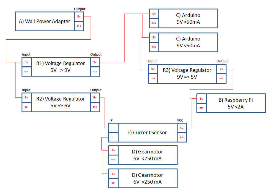
Is this a recommended layout?
I thought about using the regulator built into the A*, but that doesn’t help with the Pi. I am hoping the current sensor can detect an unexpected stall fast enough to trigger a halt before the processors loose power. I might upgrade to a 5A adapter once I am comfortable with the 3A.
A) Wall Power Adapter: 5VDC, 3A, 5.5×2.1mm Barrel Jack, Center-Positive (Pololu - Wall Power Adapter: 5VDC, 3A, 5.5×2.1mm Barrel Jack, Center-Positive)
B) Raspberry Pi: Consuming 5V at <2A
C) Arduino: Consuming 7V-12V at <50mA each
D) 391:1 Metal Gearmotor 20Dx46L mm 6V CB, Consuming 6V at 0-250 mA each (Pololu - 391:1 Metal Gearmotor 20Dx46L mm 6V CB)
E) ACS714 Current Sensor Carrier -5A to +5A (Pololu - ACS714 Current Sensor Carrier -5A to +5A)
R1) Pololu 9V Step-Up Voltage Regulator U3V50F9, Max 5A input, 9 V Output (Pololu 9V Step-Up Voltage Regulator U3V50F9)
R2) Pololu 6V Step-Up Voltage Regulator U3V50F6, Max 5A input, 6 V Output (Pololu 6V Step-Up Voltage Regulator U3V50F6)
R3) Pololu 5V, 5A Step-Down Voltage Regulator D24V50F5, Max 5A input, 5 V Output (Pololu 5V, 5A Step-Down Voltage Regulator D24V50F5)
(EDIT: Added part numbers for regulators)
Hello.
Are you using motor drivers to drive both your motors? I do not see any drivers in your diagram or any mention of using them. (You cannot drive a motor directly from a microcontroller.) If you have not already purchased the items you listed, you might consider using our motor drivers with built-in current sensing. If you are using motor drivers and the current sensor is connected to the motor driver’s power input, then your plan looks fine.
Are you currently using A-Stars? If so, which ones? Also, is there a particular reason why expect your controllers to be particularly sensitive to motor noise?
By the way, since you’re using low current motors and already have a regulator connected between your power supply and motors, you probably don’t need the 5V, 5A Step-Down Voltage Regulator D24V50F5 (R3); you could try powering the Raspberry Pi directly from your power supply.
- Amanda
Thanks Amanda!
I was planning on using motor drivers, and should have included them in the diagram. I hadn’t known about the current sensing ability of some of the motor drivers. That’s a fantastic idea, and it simplifies things a lot 
I wasn’t expecting too much motor noise with the low current motors, but I was hoping to scale up the power as part of the prototyping process. I wanted to get the power design right first. I’ve noticed a few blog posts that warn against running a Pi on the same power line as the motor drivers, and I figured it was best practice to isolate them.
Are you saying it is ok to have the Wall Power Adapter (A) drive both the Raspberry Pi (B) and the Voltage Regulator (R2) that goes to the VMM of the motor drivers? If the motor load spikes, then the regulator prevents that spike from hitting the Pi?
Yes, it seems fine to power both the Raspberry Pi and the regulator (R2) connected to the motor power input directly from your wall power adapter. The regulator (R2) will absorb some of the electrical noise from the motors, but how well it works will depend on the amount of noise there is. You could try testing without the step-down regulator (R3) just to keep things simple and then add the regulator if needed.
- Amanda
Perfect. Thanks for your help!