Hi,
completely new to this but I have been building animatronic figures for my models using a standard RC receiver and servos. The idea of have a figure perform a series of programmed movements using a single channel really appeals but if I am honest I am a bit stumped on where the connections should go.
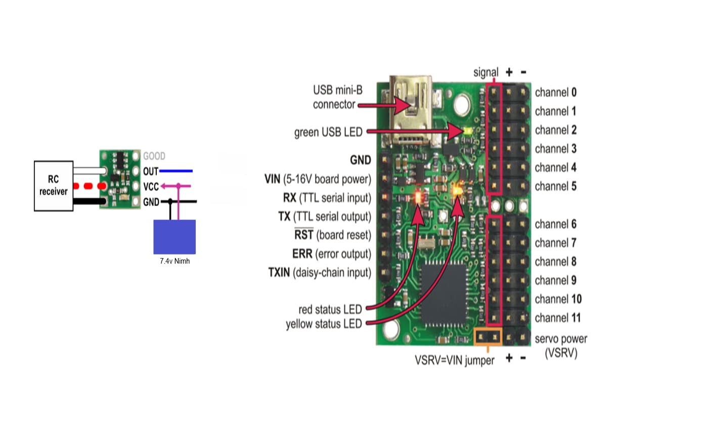
Here is what I am trying to achieve. Pololu switch, maestro 12 channel controller,
Single power supply. ( 7.4v Nimh)
Would this work? I am after a switchable power/signal to the maestro so that when I flick a toggle switch on the transmitter the servo sequence plays on the maestro
Hello.
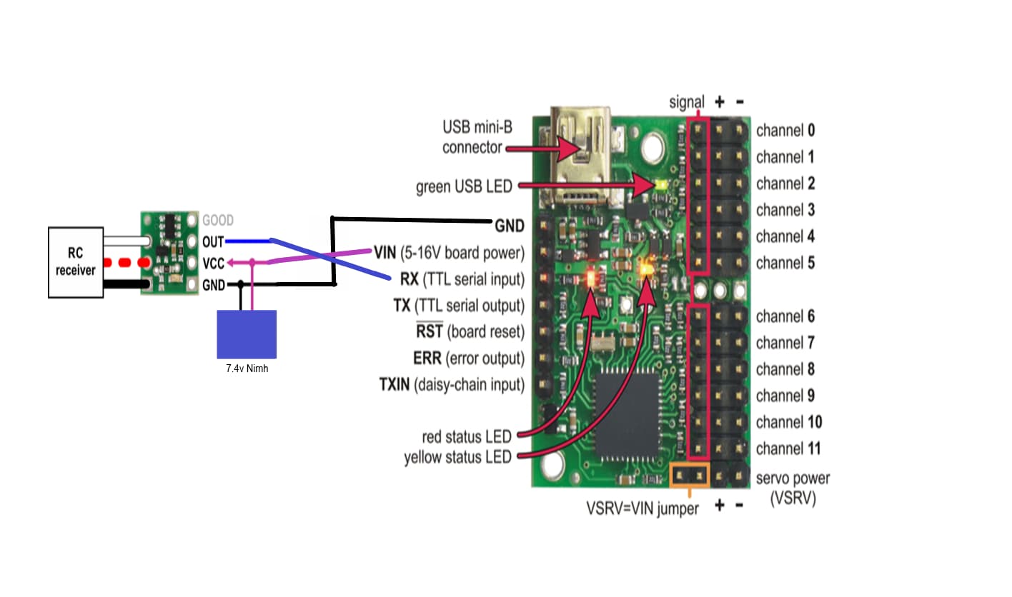
The operating voltage for the RC Switch with Digital Output (i.e. the VCC connection) is 2.5-5.5V, so you should not power it from your 7.4V battery. Also, it does not make sense to connect the OUT pin from the RC switch to the RX pin on the Maestro. Just to clarify, are you trying to power the whole setup from your 7.4V battery (i.e. the Maestro, servos, RC switch, and RC receiver)? Also, do you have any servos or other devices connected to your RC receiver?
Brandon
Hi Brandon,
Thanks for getting back to me.
The usual set up in my models:
I was hoping to power the whole set up from the battery in the model. The idea being a single channel from the receiver would activate the maestro to perform a pre programmed sequence of movements in the driver (animatronic)
Number of servos? Dependant on the type of model. Wheeled vehicles usually would only have 3 other servos: Speed, steering, sound. Tracked vehicles could have up to 6 other servos.
Power to pololu switch : So, if I placed a bec with an output of 5v direct from the battery to the pololu switch would that be suitable? Would the maestro still require a separate power supply?
As I said, I am completely new to this type of electronics and really have no idea what should be connected where!
Thank you for your patience
Best regards
Juggy
Hello.
Thank you for the additional information.
The RC switch can be powered from 5V, either from a BEC or from one of the Maestro’s regulated 5V output pins (for the 12-channel Maestro, you can refer to this diagram from the product page).
For the Maestro, if you have not already done so, I recommend reading through the “Powering the Maestro” section of the Maestro user’s guide. In short, you will need to power the Maestro’s logic side (which can be done through the VIN pin from a 5-16V source) and the servo power rail. If you use a voltage that is appropriate for both the Maestro and your servos, you can supply power to the servo power rail and use the VSRV=VIN jumper to power the Maestro’s logic side from the same supply.
The “OUT” signal from the RC switch should be connected to the signal pin on one of the Maestro’s servo channels that is configured as an input. You can configure the desired channel as an input from the “Channel Settings” tab of the Maestro Control Center. After that, you can program the Maestro with a script that monitors the configured input channel and runs your sequence when it detects the input. You can find some sample scripts in the “Example Scripts” section of the user’s guide for using a button (which is essentially the same, but you probably don’t need to worry about debouncing). However, before you get to programming the Maestro, I recommend verifying the setup is working by looking at the “Status” tab of the Maestro Control Center while triggering the RC switch to make sure the input channel reacts as expected.
If you are still unsure about all the required connections, you can post an updated diagram and I would be happy to take a look.
Brandon
Thanks Brandon,
I am away for the weekend at Tankfest so I will try this out next week.
Kind Regards
Juggy
1 Like
Hi Brandon.
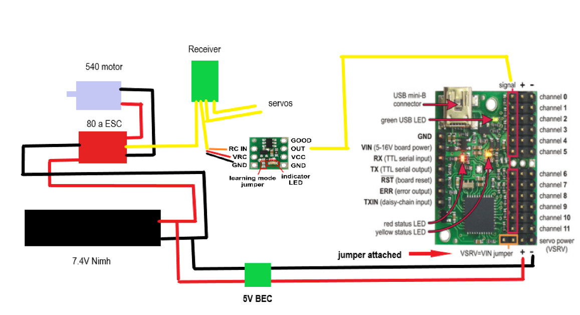
This is the set up so far.
- Jumper attached.
- In normal RC the reciever would supply power to the servos in the model, will this work for the switch or does it require it’s own power supply?
- Out from the switch to channel 0 signal pin on the maestro reconfigured as input.
- I do not know where the other outputs on the switch need to be connected.
Thank you for your patience
Regards
Juggy
Hello, Juggy.
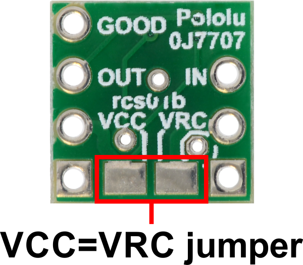
To clarify, the VRC pin on the RC switch is not connected to anything else on the board by default. To power the board, you can either use the VCC pin or bridge the VCC=VRC jumper pads on the underside of the board shown below:
The GOOD pin is an optional output that indicates the presence of a valid RC signal on the RC IN pin, and both of the GND pins on the board are connected internally.
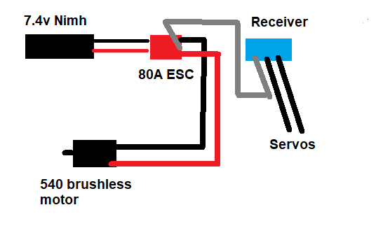
It is not indicated in your diagram, but it looks like you have the receiver and RC switch getting power from a 5V BEC that is built into your ESC. Is that the case? Are the servos connected to your Maestro safe to run on a 7.4V battery directly? (Most standard servos are intended for 4.8-6V nominally.)
Brandon
Hi Brandon,
- Sorry, forgot to add the BEC from the battery in my diagram.
- If I bridge VCC=VRC then the rc receiver will power the switch?
- The only connection I need from the switch to the maestro is OUT to the signal pin, designated as input, on the maestro? Or should I use the GOOD pin?
Apologies for being a complete biff on this.
Best regards
Juggy
The GOOD pin is an optional output; if you do not need to monitor that your RC signal is valid, you do not need to connect it.
It is still not clear to me what voltage is powering your receiver and RC switch (i.e. the VRC pin) from that diagram. Is it coming from your ESC?
Brandon
The ESC powers the receiver and all servos connected to it. This is the standard set up in all my models. I therefore assumed the switch would also draw its power via the receiver connection?
What voltage is the ESC providing? If it is higher than 5.5V then it is not appropriate for powering the RC switch (in which case you can power it using the 5V from your BEC instead).
Brandon