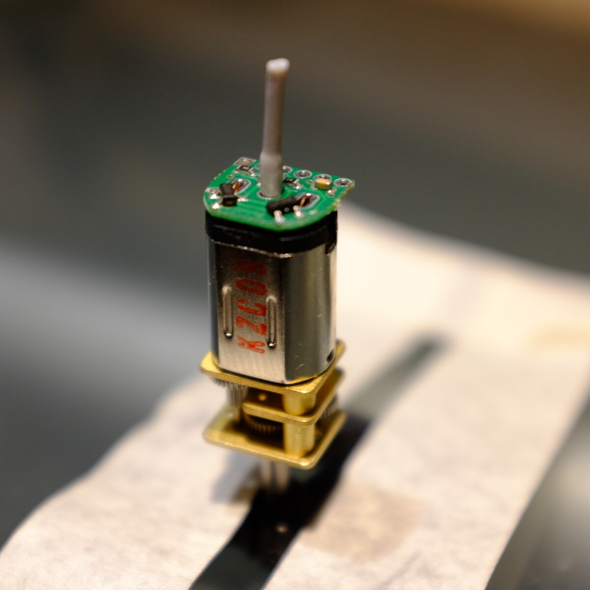
I think I just invented a new technique. One of the trickier solder jobs ever is soldering the tiny encoders on the end of a micro metal gearmotor. It has to be centered over the shaft and both the motor and the encoder are tiny.
What I did was take some 26 gauge silicon wire, strip a bit of insulation, and push the empty bit of insulation (a hollow silicon tube) down onto the shaft until it was pressing firmly against the little PC board, holding it in place. I then checked that the board was centered and pushed the motor into a Pololu wheel taped to my desk to provide a stable base. I then solder-tacked one contact, then soldered both of the contacts properly with a nice bit of hot flow. Easy!
4 Likes
That’s a fun tip! Thanks for sharing. With the size of these boards, keeping it aligned while trying to solder the motor terminals can definitely be tricky without a dedicated setup. Usually, I like to tin the motor terminals, then hold the board aligned with one hand while tacking the terminals to the board. Then, once it is held in place, I can go back and add more solder.
By the way, in case you have not seen them yet, we recently released versions of these encoders with top-entry connectors or side-entry connectors, which work with our corresponding removable JST SH-type cables and removes the need to solder to the 2mm pitch pins!
Brandon
Hi Brandon, yes I’m aware of the top- and side-entry versions of the encoders, but for this project I’m installing the motors on a Zumo, and there’s AFAIK not enough room for those without judicious use of a Dremel to clear the way, a suggestion one of Pololu’s tech support suggested to me about a year ago. I’m currently trying to figure out how to build the Zumo but not solder the shield to the motors, so that I can theoretically remove the shield later and try a different controller. What I’ve found is that the Zumo design isn’t really suited for that. But that is likely a different subject of discussion…
Cheers
1 Like
Thanks for the explanation; that makes sense. The original Zumo for Arduino was not really designed to work with encoders so it generally takes some chassis modification to get them to fit. However, in case you weren’t aware, the Zumo 32U4 Robot does support encoders.
You might be able to route some wires from the motors to the top of the Zumo so you can use some header pins to connect them to the motor outputs. But as you said, that might require some heavy modification of the chassis. If you come up with a way to connect the motors to the shield without directly soldering, we would love to see it!
Brandon
Hi Brandon,
Yes, I’d considered the 32U4 as it has more features than the shield, but I was looking for a kit as I’m experimenting with a way to not have to permanently mount the shield to the chassis so I can try out an RP2040-based robot controller as an alternative to the Arduino shield on the same chassis. I’m investigating the idea of a club robot for the New Zealand Personal Robotics Group (NZPRG), one that can be programmed in some flavour of Python rather than the Arduino’s C/C++, as I think that’d be a lower barrier to entry for some people, and Python is nowadays both a good entry into programming as well as a key job skill.
I went to bed last night after declaring victory, having figured out a way to mount the motors and route the encoder wires. The latter was trickier than I’d thought, as there’s not many places where twelve 26ga wires can exit that tiny cavity and manage to get out and up onto the shield, especially since: a. the plastic pieces and the shield fit snugly to the top of the chassis, with no room for wires between; and b. I’m planning to mount the IR sensor array, whose double-row female connector fits snug up against the front of the chassis. There was only one direction left and that was down.
I cut two small rectangular holes right below where the encoder PC boards are located, soldered the encoder wires to the PC boards, very carefully bent those wires 90 degrees (perpendicular) away from the motors, then inserted them through the holes and guiding the motors into place.
I posted photos of the results in the #build-photos channel of the Personal Robotics server on Discord, which I started a few weeks ago. In you or anyone else at Pololu are interested, here’s an invitation to Personal Robotics:
https://discord.gg/6RyZ7Bae
(This URL will be good for one week, after which please contact me for a new one.)
Cheers,
Murray
1 Like
Nice job; It looks like you’re off to a good start!
By the way, if you are looking to build a general purpose robot (and not specifically a sumo robot), our Romi chassis with the Romi 32U4 Control Board might be an option. The Romi 32U4 Control Board was designed to be easy to interface with a Raspberry Pi to expand on the processing power. This setup allows the Romi 32U4 control board to act as an auxiliary controller, communicating with the Raspberry Pi through I2C. You can find more information in the “Raspberry Pi interface and level shifters” section of the Romi 32U4 Control Board user’s guide.
Brandon