Hi guys,
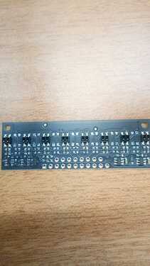
Got the new QTR sensor and want to know and compare it with my previous one…QTR 8A
Looking at the new range of QTR sensors, one thing that caught my interest was that the boards can be powered by any voltage between 2.9v and 5.5v, this could be really useful for many situations…
when I looked at the schematic of ‘A’ series sensors (link below), the V IN is directly connected to the emitter… does this mean that 5.5v is connected to emitter? or any kind of power regulator or buck converter is employed to regulate the voltage? what is the value of V IN? and I don’t get what is the current source doing there?
sorry for a ton of questions, getting started with robotics…
link:
Pololu - QTR-MD-01A Reflectance Sensor: 1-Channel, 7.5mm Wide, Analog Output
summarized…before I
- 32 levels of brightness control
- input voltage from 2.9v to 5.5v
is there any other change? new sensor or the same QRE1113
Hello.
It looks like you are using our schematic for a single sensor, but you might also want to check out our more complete schematic which is available on the product page under the resources tab. VIN, which can be anywhere between 2.9V and 5.5V is connected to the directly to the emitter, and there is an LED in series with the emitters that controls the current through them.
There are two other big changes that you did not mention. First, we also have versions of these products that use a higher-performance sensor with lenses on the IR emitter and phototransistor, which we are calling QTRX. These higher-performance sensors allow similar performance at a much lower IR LED current, which can really start adding up at higher channel counts. Second, many of the new QTR and QTRX boards (though not the particular board you have) allow for independent control of the odd and even IR emitters.
We do not commit to a particular component, but we are currently using a generic alternative to the QRE1113 with a slightly longer range.
- Patrick

