
My new orangutan, purchased from robotshop.ca, has only 1 line of active lcd display, the other is blank and the faint background squares don’t light up! What’s up? Can I get it replaced?
Hello.
First of all, which specific Orangutan model did you purchase? Can you post the code you’re using to try to write to the second line of the display? We test all our products before they ship, so it seems more likely that your problem is from incorrect LCD code. For example, are you assuming that if you write a string of 10 characters to the LCD, you will see the first eight characters on the top line and the last two characters on the bottom line?
- Ben
Yes, I was very surprised to find this, and I don’t remember if the default code had the problem, but it is currently running the Orangutan Lib lcd test program:
// lcd-test
//
// Tom Benedict

// This example demonstrates most of the functions of the LCD
// subsystem.  Since the Baby-Orangutan has no LCD, this example
// will only work on the Orangutan or the Orangutan-X2.

// Include our I/O definitions
#include <avr/io.h>

// Include information about the device we're building for
#include "device.h"

// Include for using delay routines
#include <util/delay.h>

// Include for the LCD subsystem
#include "lcd.h"

// Delay for N seconds
void delay_sec(unsigned char sec)
{
	unsigned int cycles;

	// Delay 25ms at a time (38.4ms is the most we can delay with a
	// 20MHz processor, unfortunately.  See the delay.h include file
	// for more info.)

	for(cycles = 0; cycles < (sec * 40); cycles ++)
	{
		_delay_ms(12);
		_delay_ms(13);
	}
}

// And now for our main routine:
int main(void)
{
	int i;

#ifdef _ENABLE_LCD_

	// Initialize the LCD
	lcd_init();

	for(;;)
	{
		// Startup Banner
		lcd_clear();
		lcd_gotoxy(0,0);
		lcd_string("LCD");
		lcd_gotoxy(0,1);
		lcd_string("Test...");
		delay_sec(2);

		// Test multiline display
		lcd_clear();
		lcd_gotoxy(0,0);
		lcd_string("Line 1");
		lcd_gotoxy(0,1);
		lcd_string("Line 2");
		delay_sec(2);

		// Test cursor hiding
		lcd_clear();
		lcd_gotoxy(0,0);
		lcd_string("Hide");
		lcd_hide();
		delay_sec(2);
		lcd_gotoxy(0,1);
		lcd_string("Show");
		lcd_show();
		delay_sec(2);

		// Now hide it 'cause it's annoying
		lcd_hide();

		// Scroll left
		lcd_clear();
		lcd_gotoxy(0,0);
		lcd_string("Scroll");
		lcd_gotoxy(0,1);
		lcd_string("Left");
		delay_sec(1);
		for(i=0; i<=LCD_MAX_X; i++)
		{
			lcd_shift(0, 1);
			delay_sec(1);
		}

		// Scroll right
		lcd_clear();
		lcd_gotoxy(0,0);
		lcd_string("Scroll");
		lcd_gotoxy(0,1);
		lcd_string("Right");
		delay_sec(1);
		for(i=0; i<=LCD_MAX_X; i++)
		{
			lcd_shift(1, 1);
			delay_sec(1);
		}

		// Show the cursor again
		lcd_show();

		// Cursor left
		lcd_clear();
		lcd_gotoxy(0,0);
		lcd_string("Cursor");
		lcd_gotoxy(0,1);
		lcd_string("Left");
		lcd_gotoxy(7,0);
		delay_sec(1);
		for(i=0; i<=LCD_MAX_X; i++)
		{
			lcd_moverel(0, 1);
			delay_sec(1);
		}

		// Cursor right
		lcd_clear();
		lcd_gotoxy(0,0);
		lcd_string("Cursor");
		lcd_gotoxy(0,1);
		lcd_string("Right");
		lcd_gotoxy(0,1);
		delay_sec(1);
		for(i=0; i<=LCD_MAX_X; i++)
		{
			lcd_moverel(1, 1);
			delay_sec(1);
		}

		// Hide the cursor again
		lcd_hide();

		// Moveto (butterfly pattern)

		lcd_clear();
		lcd_gotoxy(0,0);
		lcd_string("Move-To");
		lcd_gotoxy(0,1);
		lcd_string("Testing");

		for(i = 0; i < 4; i++)
		{
			lcd_moveto(1, i);
			lcd_string("#");
			lcd_moveto(1, 7-i);
			lcd_string("#");
			lcd_moveto(2, i);
			lcd_string("#");
			lcd_moveto(2, 7-i);
			lcd_string("#");
			delay_sec(1);
		}

		delay_sec(2);

	}

#endif // _ENABLE_LCD_

	// We never get here, but return a zero if we ever do.
	return 0;
}
It is the Orangutan mega168 (https://www.pololu.com/catalog/product/225).
Oh, and about the wrap, no, I was just testing the display. I was just wondering why the second line didn’t show anything, but then I saw that the second line didn’t have the ‘background’ (for lack of a better word).
I probably won’t have a chance to take a look at this until monday, but I suggest you keep playing around with it as I’m not sure how reliable the lcd test program you’re running is. It might also help if you could post a picture of your LCD and its missing background.
- Ben
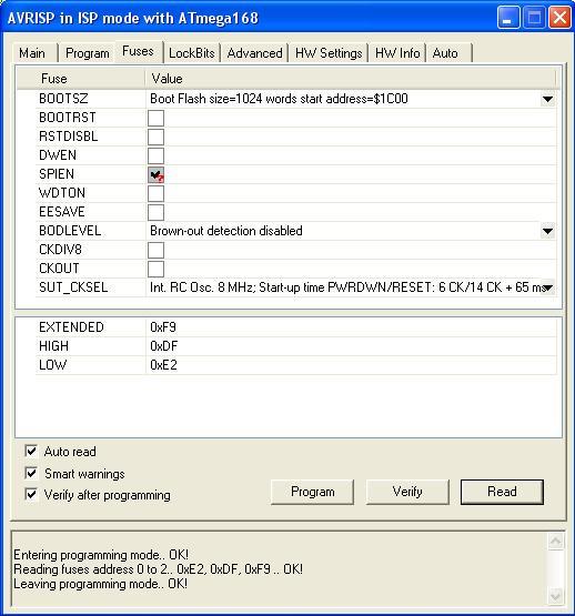
The Orangutan-Lib demo code assumes that your Orangutan is running at the internal oscillator’s full 8MHz, but if I remember correctly, the ATMega168’s ship with the “Divide Clock by 8 internally” fuse set, so yours is probably running at 1MHz. I just tried that on my Orangutan, and I think I’m seeing what you’re describing. Only the first line displays text, and it has an extra-high contrast dark background, while the second line is completely blank.
If you like you can change the clock speed definition in device.h, but I think the better thing to do is to set your Orangutan to operate at its full 8MHz speed. More example code will work for you that way, and you get 8-times faster program execution! You should always be careful changing fuses though, you can mess things up in a way that’s hard to undo! (Like setting your clock source to something other than the internal oscillator, which is all your Orangutan has installed right now!).
In the programming window, go to the “Fuses” tab. If the option “Divide clock by 8 internally” is checked, un-check it and click Program. Again, be careful not to change any of the other fuse settings.
Did that do it?
-Adam <-who failed to take his own advice, accidentally set the wrong fuse, and has to wire up a low-frequency external crystal oscillator to recover his Orangutan now
lol, was that because of this?
Anyways. I’m on a mac. So I get a terminal window  .
.
As for the device.h thing… I’m using the orangutan line and the timer 2 line. Not sure if that is what you mean or not. This one line thing also happens when I run servo-test… which also doesn’t work btw.  Expect a thread on that in the near future.
Yeah, I was being careless and instead of un-checking “Divide clock by 8 internally” I checked “Ext. Clock” and hit program. I do have an external crystal oscillator on the back of my Orangutan, but now I need to de-solder that and hook up an external clock source to be able to set the fuses back. Let this be a lesson.
Anyway, I’m not sure how you would change fuse settings with your setup, maybe someone else here can help you with that.
In the meantime you could change your clock speed definition. In device.h, try changing:
#ifdef ORANGUTAN

#ifndef F_CPU
#define F_CPU 8000000UL
#endif //!F_CPU
to:
#ifdef ORANGUTAN

#ifndef F_CPU
#define F_CPU 1000000UL
#endif //!F_CPU
That should take care of any delay-based timing issues, like the LCD problem, but you still might have trouble with timer/interrupt based example code. I can’t verify this one way or other until I rescue my Orangutan though!
-Adam
Nope. No luck there.
Any other help here is greatly appreciated.
EDIT: Changed the wrong device.h file (Doh!) but still nothing, just runs faster (about 8X maybe  )
)
PIC, to show what I mean: (copy and paste, img won’t work, link doesn’t load because of freehostia) 1244robotics.freehostia.com/orangutan1.gif
PS, that’s my site too, eh. Go 1244!
I’ve caved, I’m downloading AVR studio. I’ll try wine, and if that doesn’t work I’ll use parallels. I’ll try some of the stuff you suggested now.
EDIT: No I won’t. It doesn’t work under wine OR parallels, didn’t expect that. Oh well.
Your mirrored Orangutan image was confusing me there for a second.
Anyway, it’s odd that your code would execute faster (indicating you did change clock speed definition in the right place) but the screen still wouldn’t work. As soon as I get my Orangutan back in action I’ll check it out, but it looks like the LCD code in Orangutan-Lib (and the servo code for that matter) should work fine with just a proper clock speed definition. If you want to be sure that you’re getting the right speed, you can always add the line:
#define F_CPU 1000000
To the very top of your main program file, before the include statements. This will override the settings in device.h.
Yeah, I’ll be really happy the day AVR Studio works with Wine. Or they just make a Linux version. There’s an ATMega8-based tutorial on setting AVR fuses using AVRDude here. It looks a little risky though, you’ve seen what a mis-set fuse can do to your (my) Orangutan! Maybe just use it to check your fuse settings, and see what your clock speed is set to. If you ever do need to make fuse changes, I would try to borrow to a Windows computer just long enough to install AVR studio and change the fuse settings.
-Adam
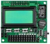
Okay, I managed to revive my Orangutan, and I’m pretty certain now that the “Divide by 8” fuse is your whole problem (with the servo control sample code too). I took these pictures just now:

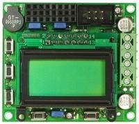
The one on the left is what my Orangutan looks like with the “Divide by 8” fuse set, even if I correctly define the CPU frequency as 1MHz. The one on the right is the same code running at 8MHz, with the “Divide by 8” fuse cleared.
A lot of the Orangutan-Lib sample programs rely on your Orangutan operating at either 8 or 20 MHz, and changing the clock definition alone doesn’t seem to fix that. You can control servos and the LCD with the Orangutan operating at 1MHz, but you’re going to have to do some more editing of the Orangutan-Lib code. Orangutan-Lib is a great resource though, and changing that fuse setting (either through AVRDude or by borrowing a Windows computer briefly) seems like a much better way to go to me.
-Adam
So, I only have to set the fuse setting once and its set for good, right?
What about the servo issue, any ideas?
I took a look at the Orangutan-Lib servo library, and its based on an assumption of either an 8MHz clock speed (original Orangutan) or a 20MHz clock speed (Baby Orangutan, Orangutan X2), regardless of the F_CPU defined clock frequency. Looking at the output signal confirms this.
So yes, you only have to clear the “Divide clock by 8 internally” fuse once, and it will stay that way. You shouldn’t have to mess with the fuse settings again after this, unless you’re doing something exotic like adding an external crystal clock. And yes, this should make the Orangutan-Lib servo functions run properly on your Orangutan as well.
-Adam
Sweet. I’ll install AVRStudio and do that tonight.
Thanks Adam, you’ve been a HUGE help.
Hi,
sorry to open up this thread again, but I’ve just bought an Orangutan atmega168 controller and having similar issues. Im only getting the top line of text showing on the LCD, the bottom line is completely blank - I’ve never actually seen it show any kind of life at all.
Im using the “lcd-only” code from the “orangutan-examples-01” posted on sourceforge. all other examples I’ve tried dont work for me at all.
The divide by 8 fuse is un-checked and I dont appear to be having any contrast issues.
does anyone out there have any suggestions for me to try? This is the first time I’ve played with this unit so its a fair chance its something simple I’m missing!
Im using AVR studio 4.
thankyou.
I wish I could remember what I did…
I guess try changing the clock speed in device.h, I’m pretty sure it isn’t set to orangutan by default, baby-o, i think.
unfortunately not the issue here, this code doesnt have a device.h file, everything is written in a single file.
the clock speed is set at 8MHz.
hmmmm, again, I wish I could remember what I did…
Sorry you’re having trouble, but the fact that the LCD is working at all is a good sign.
Do you have the original Orangutan mega168:
or the Orangutan LV-168:
?
And which fuses are checked if you “Read” them back in AVR studio?
Also, are you seeing the first line run through the different words (Hide, Scroll, Cursor, etc…), or is the display just showing one word for as long as you leave it on?
-Adam
P.S. One last thing to try, what happens if you physically disconnect the programmer, then switch power off and back on? AVRISP programmers reset their target microcontrollers after programming them, and sometimes that can mess with time-based operations like the LCD initialization routine.
Hi Adam, thankyou for your suggestions.
I am using the original orangutan mega 168 (same as the top image you posted).
the only fuse set is the SPIEN which is checked, but also has a question mark there also?
the program appears to be running correctly, it is scrolling, hiding, showing, etc in the test loop, however I only see the top line displayed.
also, no change when I disconnect the programmer, and when I turn the unit off the code is lost as Im storing it in flash.
// lcd-only
//
// Tom Benedict


// This is a set of routines to drive the 8x2 LCD display on the
// Orangutan controller.  The Baby-Orangutan does not have an
// LCD on it and I'm not aware of the Orangutan X2's LCD setup
// yet, so for the moment this example is strictly for the
// Orangutan.
//
// The Orangutan drives the LCD in 4-bit mode with E, R/W, and
// RS control lines.  Here are the pin assignments:
//
// AVR		LCD		Direction		Function
// ------	------	--------------	----------------------------
// PD4		E		Out				Dedicated to LCD Enable
// PD2		RS		Out				Dedicated to LCD ???
// PD3		R/W		Out				Dedicated to LCD Read/Write
// PD7		DB7		In/Out			Dedicated to LCD I/O
// PB5		DB6		Out				LCD I/O and Orangutan SW5
// PB4		DB5		Out				LCD I/O and Orangutan SW4
// PB3		DB4		Out				LCD I/O and Orangutan SW3
// N/C		DB3
// N/C		DB2
// N/C		DB1
// N/C		DB0


// As you can see, three of the four data lines are also tasked to
// the three push buttons on the Orangutan.  What this means is that
// we need to keep track of this and that we can't use the buttons
// when the LCD is being written to.  We have no gurantee what state
// those lines are in, so we need to return them to whatever state
// they were in once we're done using them.
//

// So let's get to it!


// Declare your CPU speed based on which device you're using
// Just uncomment the value for F_CPU that corresponds to the
// device you're building for:

// The Orangutan is an 8MHz device
#ifndef F_CPU
#define F_CPU 8000000UL
#endif //!F_CPU
// #define F_CPU 8000000UL

// The Baby-Orangutan is a 20MHz device
// So is the Orangutan-X2

// #define F_CPU 20000000UL


#include <avr/io.h>

// Unlike most of the other examples, the LCD relies heavily on
// delays.  So it's required to set F_CPU and include <util/delay.h>
// not just for the purpose of this demonstration, but for the LCD
// code to work at all.
#include <util/delay.h>


// Because the LCD routines don't have exclusive rights to PB3, PB4,
// and PB5, we need to declare a mask we can use to toggle the state
// of those pins in the data direction register.  Likewise, since
// we're going to use PD7 as both input and output, we need to
// declare a mask for PORTD so we can toggle the input/output bit in
// DDRD.

// Port Masks

#define PORTB_MASK		0x38	// PB3, PB4, PB5
#define PORTD_MASK		0x80	// PD7

// Since we're only using four data lines, and since the pins they're
// wired up to don't start with 0, we need to shift them into
// position in order to load their values into the LCD.  Port B uses
// bits 3, 4, and 5, so we take our data and shift it by three
// positions to make things line up.  At that point our data
// looks like this:
//
//	PortB:     7 6 5 4 3 2 1 0
//  LCD Data:    3 2 1 0
//
// The last bit for the LCD needs to go out PortD on pin 7, so we
// do one last shift to make its data line up.
//
// Sorry this is so confusing.  It'll make more sense in the
// lcd_nibble() routine, which is where these shift values
// actually get used.

#define PORTB_SHIFT		3
#define PORTD_SHIFT		1

// Just in case the Orangutan X2 uses a different setup for its LCD,
// declaring the control pins here will make it easier to set the
// code up to compile for it at a later date.

// Control Pins

#define LCD_RW			PD3
#define LCD_RS			PD2
#define LCD_E			PD4

// These commands are all straight out of the data sheet for the LCD
// installed on the Orangutan.

// Commands

#define	LCD_CLEAR		0x01
#define	LCD_LINE1		0x02
#define LCD_LINE2		0xC0
#define LCD_SHOW_BLINK	0x0F
#define LCD_SHOW_SOLID	0x0E
#define LCD_HIDE		0x0C
#define LCD_CURSOR_L	0x10
#define LCD_CURSOR_R	0x14
#define LCD_SHIFT_L		0x18
#define LCD_SHIFT_R		0x1C

// Usually I try to put initialization routines first in the list,
// but the LCD requires its communication routines to be
// established before you can initialize it.  So we'll start
// with the basic communication routine:  Send a four-bit nibble
// to the LCD.
//
// lcd_nibble() assumes ports B and D already have their DDR set
// correctly, and assumes PD7 is an output.  It's the job of the
// routines that call lcd_nibble() to make sure these conditions
// are met.

void lcd_nibble(unsigned char nibble)
{

	// Make sure our nibble really is a nibble.  This chops off
	// the high four bits of the data we're given.
	nibble &= 0x0F;

	// Shift our nibble so bits 0, 1, and 2 line up with PB3, PB4,
	// and PB5:

	nibble <<= PORTB_SHIFT;

	// Clear those bits out of PORTB so we can write into them:

	PORTB &= ~PORTB_MASK;

	// And load PORTB with those three bits:

	PORTB |= (nibble & PORTB_MASK);

	// Now shift our nibble so bit 3 lines up with PD7:

	nibble <<= PORTD_SHIFT;

	// Clear that bit out of PORTD so we can write into it:

	PORTD &= ~PORTD_MASK;

	// And load pORTD with that last bit:

	PORTD |= (nibble & PORTD_MASK);

	// Delay for 1ms so the LCD can register it's got the nibble:

	_delay_ms(1);

	// At this point the four data lines are set, so the Enable pin
	// is strobed to let the LCD latch them.
	//
	// The LCD device is highly dependent on delaying for a proper
	// length of time.  For a 20MHz device, 5 clock cycles is enough
	// of a delay for the LCD to latch its inputs.  Delaying too
	// long is better than not delaying long enough, so this same
	// delay should work on slower devices as well.

	// Bring E high

	PORTD |= (1 << LCD_E);
	asm(
		"nop" "\n\t"
		"nop" "\n\t"
		"nop" "\n\t"
		"nop" "\n\t"
		"nop" "\n\t"
		::);

	// Bring E low

	PORTD &= ~(1 << LCD_E);

	asm(
		"nop" "\n\t"
		"nop" "\n\t"
		"nop" "\n\t"
		"nop" "\n\t"
		"nop" "\n\t"
		::);

	// Our nibble has now been sent to the LCD.
}

// lcd_send writes one byte to the LCD (or rather, it sends two nibbles)
//
// This is the command where all the registers get saved, loaded, and
// restored at the end.  It assumes nothing about the state of ports
// B or D, and is the routine that actually sets them correctly,
// restoring them when it's done.
//
// It's this trickery that lets us have pushbuttons on the same lines
// we use to talk to the LCD.  This is neat, since we basically get
// three pushbuttons without eating up any additional I/O lines.

void lcd_send(unsigned char data)
{
	unsigned char 	temp_ddrb, temp_portb,
					temp_ddrd, temp_portd;

	// Store our port settings

	temp_ddrb = DDRB;
	temp_portb = PORTB;
	temp_ddrd = DDRD;
	temp_portd = PORTD;

	// Set up port I/O to match what the LCD needs

	DDRB |= PORTB_MASK;
	DDRD |= PORTD_MASK;

	// Send the data

	lcd_nibble(data >> 4);	// High nibble first
	lcd_nibble(data);		// Low nibble second

	// Restore our port settings

	DDRD = temp_ddrd;
	PORTD = temp_portd;
	DDRB = temp_ddrb;
	PORTB = temp_portb;
}

// The next two commands are almost identical.  One sends a command
// to the LCD.  The other sends data.  The distinction between the
// two is the state of the RS line.  For commands, RS is held low.
// For data, it's held high.
//
// One other gotcha:  The LCD takes a while to process commands.
// So the lcd_cmd() command also includes a short delay to let this
// happen before anything else is sent to the LCD.

void lcd_cmd(unsigned char cmd)
{
	// Hold RW and RS low

	PORTD &= !((1 << LCD_RW) | (1 << LCD_RS));

	// Send the command

	lcd_send(cmd);

	// Delay for 1ms to let the command process

	_delay_ms(1);
}

void lcd_data(unsigned char data)
{
	// Hold RW low

	PORTD &= ~(1 << LCD_RW);

	// Hold RS high

	PORTD |= (1 << LCD_RS);

	// Send the data.  No waits, so we can go right into sending more
	// data.

	lcd_send(data);
}

// lcd_string sends a string to the LCD.  You can send a string
// longer than 8 characters, but only eight characters show up.
// The string is printed from wherever the cursor is, and will
// not span lines.  (This lets you concatenate print statements.)

void lcd_string(const unsigned char *str)
{
	while (*str != 0)
		lcd_data(*str++);
}

// lcd_int prints an integer.  Again, this prints from wherever
// the cursor is, and will not span lines.  (This lets you
// concatenate print statements.)

void lcd_int(unsigned char n)
{
	unsigned char st[4] = {0,0,0,0};

	// The 0x30 addition shifts the decimal number up
	// to the ASCII location of "0".

	// Hundreds place
	st[0] = (n / 100) + 0x30;
	n = n % 100;

	// Tens place
	st[1] = (n / 10) + 0x30;
	n = n % 10;

	// Ones place
	st[2] = n + 0x30;

	// Print it as a string
	lcd_string(st);
}

// lcd_init initializes the LCD and MUST be called prior to
// every other LCD command.

void lcd_init(void)
{

	// This is done once, and is never checked or set afterward
	// These are dedicated lines, so this shouldn't be a problem
	// provided the rest of the program doesn't dink with it.
	DDRD |= (1 << LCD_RW) | (1 << LCD_RS) | (1 << LCD_E);

	// This next block is straight out of the data sheet for the
	// LCD.  It's how to wake up the LCD using commands rather
	// than using a specialized power-up sequence.

	_delay_ms(30);
	lcd_cmd(0x30);		// 8-bit mode (wake up!)
	_delay_ms(5);
	lcd_cmd(0x30);		// 8-bit mode (wake up!)
	_delay_ms(1);
	lcd_cmd(0x30);		// 8-bit mode (wake up!)
	_delay_ms(1);
	lcd_cmd(0x32);		// 4-bit mode

	// Now we actually set up the LCD the way we want.  The
	// controller chip inside the LCD module is actually
	// used on a number of LCDs of various sizes.  It's nice
	// since we can recycle this code for other display sizes.
	// It's not quite so nice because the controller makes NO
	// assumptions about the LCD it's driving.  You have to
	// tell it EVERYTHING.

	lcd_cmd(0x20);
	lcd_cmd(0x28);		// 4-bit mode, 2-line, 5x8 dots/char
	lcd_cmd(0x08);		// Display off, cursor off, blink off
	lcd_cmd(0x01);		// Clear display
	lcd_cmd(0x0F);		// Display on, cursor on, blink on
	lcd_cmd(0x02);		// Return home
	lcd_cmd(0x01);		// Clear display

	// At this point we're good to go.

}


// The rest of the routines for the LCD just send one of the command
// values to the LCD.  They're all listed above as #defines.  It's
// not too onerous a task to make most, if not all of these routines
// inline #defines.  But for the sake of clarity only a handful are
// written this way.


// lcd_moveto moves the cursor to the given position on the LCD
// screen.  It does this by using one of the following address
// locations on the LCD:
//
// Character	0  1  2  3  4  5  6  7
//           	------------------------
// Line 1		80 81 82 83 84 85 86 87
// Line 2		C0 C1 C2 C3 C4 C5 C6 C7
//
// It's pretty straightforward to let the programmer give us a
// line and character position, and crank out the proper
// address so they don't have to worry about it.

void lcd_moveto(unsigned char line, unsigned char pos)
{

  // In case this is the first time you've seen this notation, it's
  // a neat way of doing a comparison.  If line is equal to 1,
  // use 0x80, otherwise 0xC), and add the character position to it.

  lcd_cmd((line == 1 ? 0x80 : 0xC0) + pos);
}

// lcd_moverel shifts the cursor left or right the given number of
// positions.
//
// dir = 0	Shift left
//       1	Shift right

void lcd_moverel(unsigned char dir, unsigned char num)
{
	unsigned char cmd;

	cmd = dir ? LCD_CURSOR_R : LCD_CURSOR_L;
	while(num-- > 0)
		lcd_cmd(cmd);
}

// lcd_shift shifts the display left or right the given number of
// positions.  This is what you'd use for a scrolling display.
//
// dir = 0	Shift left
//       1	Shift right

void lcd_shift(unsigned char dir, unsigned char num)
{
	unsigned char cmd;

	cmd = dir ? LCD_SHIFT_R : LCD_SHIFT_L;
	while(num-- > 0)
		lcd_cmd(cmd);
}

// The rest of these are one-liners.  Send the appropriate command
// to the LCD, and it takes care of the rest:

// Clear the LCD

#define lcd_clear()	lcd_cmd(LCD_CLEAR)

// Move the cursor to the beginning of line 1

#define lcd_line1() lcd_cmd(LCD_LINE1)

// Move the cursor to the beginning of line 2

#define lcd_line2() lcd_cmd(LCD_LINE2)

// Show the cursor as a blinking block.  (A non-blinking cursor is
// also available.)

#define lcd_show() lcd_cmd(LCD_SHOW_BLINK)

// Hide the cursor.

#define lcd_hide() lcd_cmd(LCD_HIDE)


// That's really it for the LCD stuff (and it's plenty!).  The only
// other subroutine is a delay routine that will let us pause for a
// couple of seconds.  Almost all the example code will have this
// routine in it.

// Delay for N seconds
void delay_sec(unsigned char sec)
{
	unsigned int cycles;

	// Delay 25ms at a time (38.4ms is the most we can delay with a
	// 20MHz processor, unfortunately.  See the delay.h include file
	// for more info.)

	for(cycles = 0; cycles < (sec * 40); cycles ++)
	{
		_delay_ms(25);
	}
}

// And now for our main routine:

int main(void)
{
	int i;

        // Make sure all our registers are clear
        DDRB = 0;
        DDRC = 0;
        DDRD = 0;

        PORTB = 0;
        PORTC = 0;
        PORTD = 0;

	// Initialize the LCD
	lcd_init();

	for(;;)
	{
		// Startup Banner
		lcd_clear();
		lcd_line1();
		lcd_string("LCD");
		lcd_line2();
		lcd_string("Test...");
		delay_sec(2);

		// Test multiline display
		lcd_clear();
		lcd_line1();
		lcd_string("Line 1");
		lcd_line2();
		lcd_string("Line 2");
		delay_sec(2);

		// Test cursor hiding
		lcd_clear();
		lcd_line1();
		lcd_string("Hide");
		lcd_hide();
		delay_sec(2);
		lcd_line2();
		lcd_string("Show");
		lcd_show();
		delay_sec(2);

		// Scroll left
		lcd_clear();
		lcd_line1();
		lcd_string("Scroll");
		lcd_line2();
		lcd_string("Left");
		delay_sec(1);
		for(i=0; i<8; i++)
		{
			lcd_shift(0, 1);
			delay_sec(1);
		}

		// Scroll right
		lcd_clear();
		lcd_line1();
		lcd_string("Scroll");
		lcd_line2();
		lcd_string("Right");
		delay_sec(1);
		for(i=0; i<8; i++)
		{
			lcd_shift(1, 1);
			delay_sec(1);
		}

		// Cursor left
		lcd_clear();
		lcd_line1();
		lcd_string("Cursor");
		lcd_line2();
		lcd_string("Left");
		lcd_moveto(2,7);
		delay_sec(1);
		for(i=0; i<8; i++)
		{
			lcd_moverel(0, 1);
			delay_sec(1);
		}

		// Cursor right
		lcd_clear();
		lcd_line1();
		lcd_string("Cursor");
		lcd_line2();
		lcd_string("Right");
		lcd_moveto(2,0);
		delay_sec(1);
		for(i=0; i<8; i++)
		{
			lcd_moverel(1, 1);
			delay_sec(1);
		}

		// Moveto (butterfly pattern)

		lcd_clear();
		lcd_line1();
		lcd_string("Move-To");
		lcd_line2();
		lcd_string("Testing");

		for(i = 0; i < 4; i++)
		{
			lcd_moveto(1, i);
			lcd_string("#");
			lcd_moveto(1, 7-i);
			lcd_string("#");
			lcd_moveto(2, i);
			lcd_string("#");
			lcd_moveto(2, 7-i);
			lcd_string("#");
			delay_sec(1);
		}

		delay_sec(2);

	}

	// We nevre get here, but return a zero if we ever do.
	return 0;
}