New Mini-Sumo project

Though I still have a lot to try and learn with my RPB-202 robot, I couldn’t resist starting a mini-sumo robot project, just 'cause it looks so fun! With inspiration from excellent blog posts on the 2015 LVBots mini-sumo competition detailing the design of some of the robots, I launched the CAD software and started designing mine. I evaluated the option of using laser-cut acrylic for the chassis but ended-up choosing 3D printing as the base for the design considering it offered more design flexibility and was simpler for me to build (no need to glue and/or bend). I will build two robots so I can have them compete against each other and also so that I can get my son to compete against me!

Specifications:

Overall dimensions: W: 96mm, L: 95mm, H: 39mm (3.78" x 3.71" x 1.54" approx)
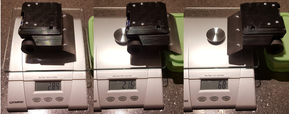
Weight: 205 g
Motors*: 2 x 75:1 Micro Metal Gearmotor HPCB 6V or 2 x 50:1 Micro Metal Gearmotor HPCB 6V with Micro Metal Gearmotor Brackets (pair).
Wheels: 2 x Solarbotics RW2 Wheel (external set screw)
Battery: 2S Li-Po 800 mAh (55 mm x 31 mm x 17 mm max size)
Microcontroller: A-Star 32U4 Robot Controller LV with Raspberry Pi Bridge (SMT Components Only)
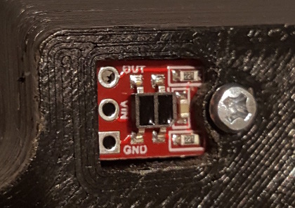
Sensors: 2 x Sharp GP2Y0A60SZLF Analog Distance Sensor, 2 x QTR-1RC Reflectance Sensors and 1 x MinIMU-9 v5 Inertial Measurement Unit.

*I bought two pairs of motors (50:1 and 75:1) and will build one robot with each set to compare which is better, speed or torque and allow use of different strategies.

Below are a few snapshots of the assembly in the CAD software:

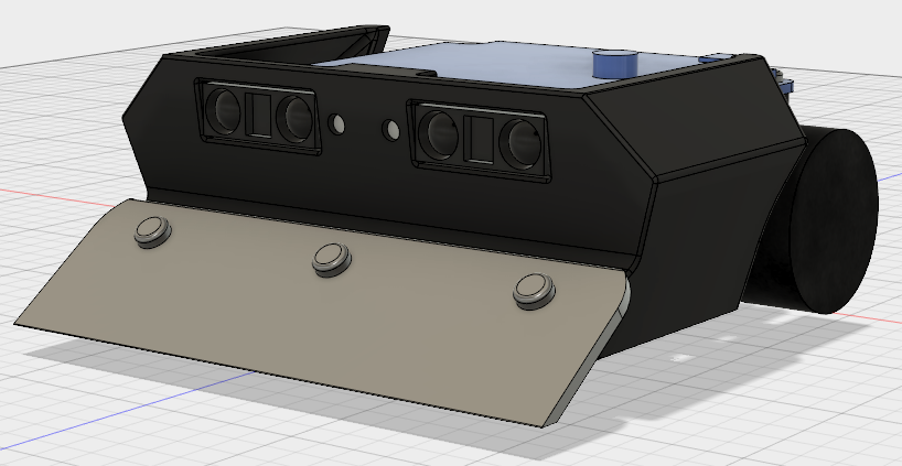
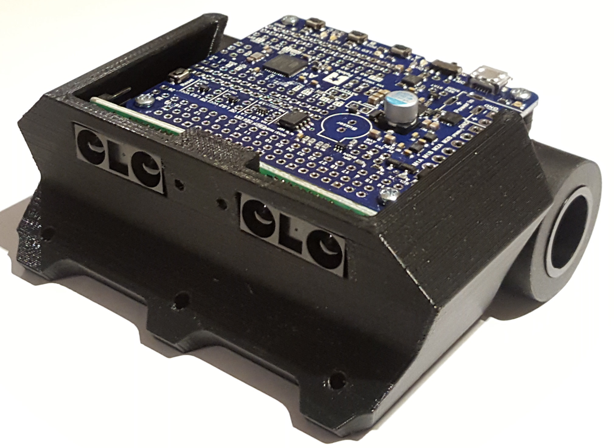
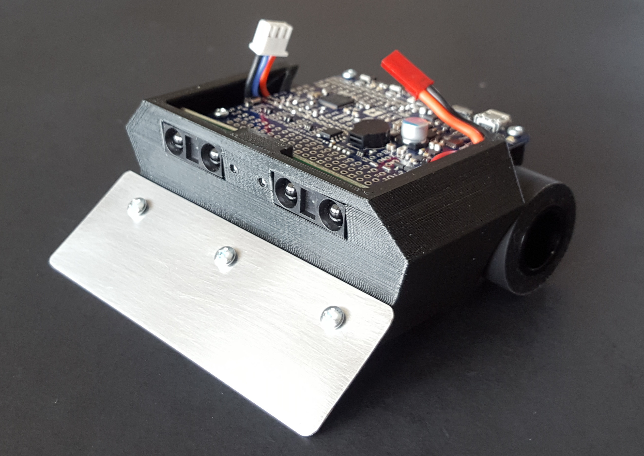
Forward view showing blade and Sharp GP2Y0A60SZLF Analog Distance Sensor

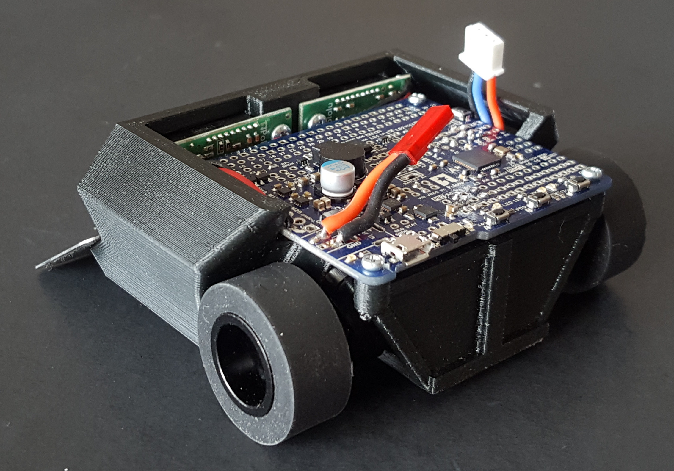
Top view showing A-Star 32U4 Robot Controller LV on top.

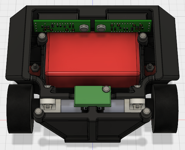
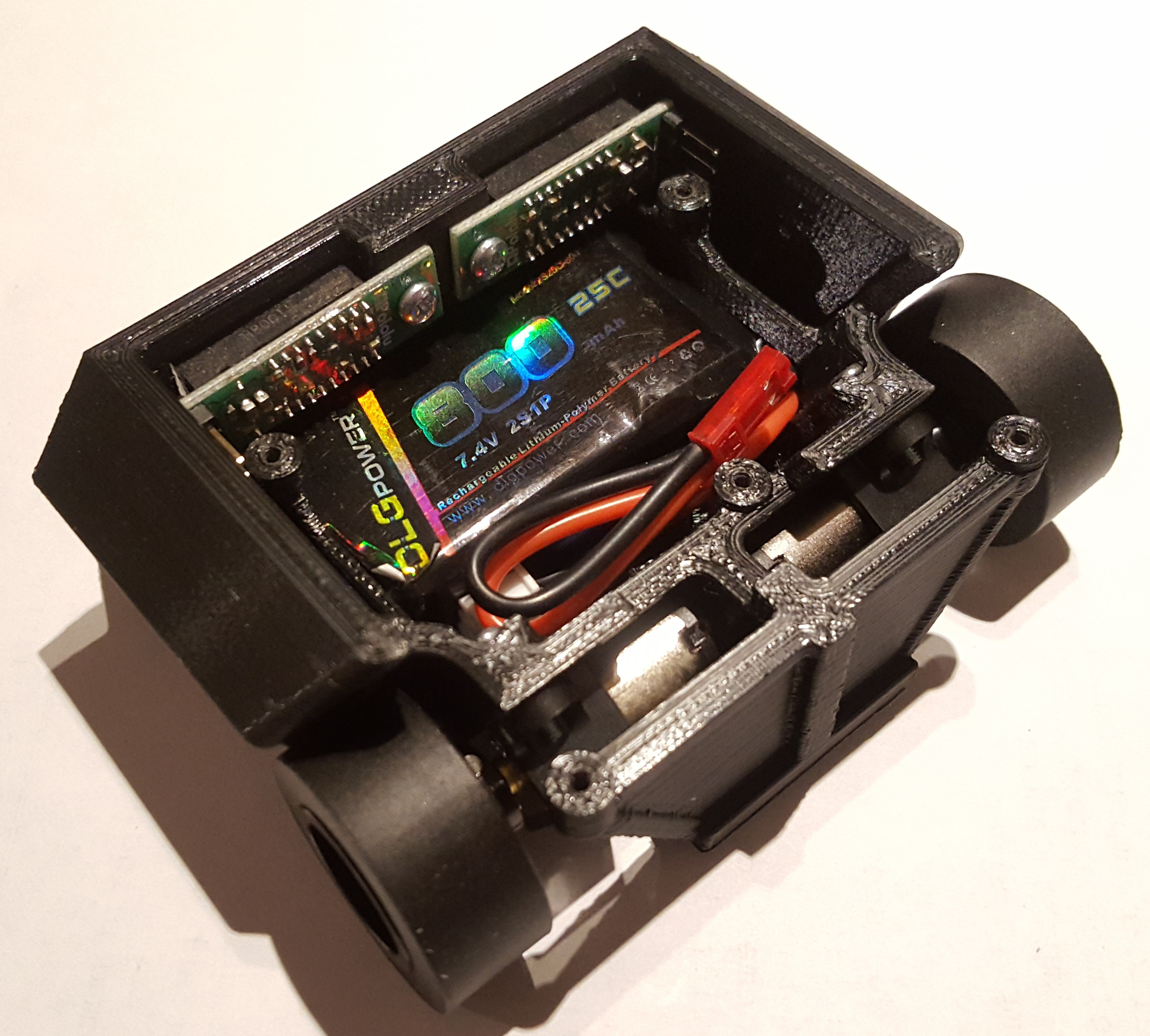
Top-rear view (with A-Star removed) showing the internals; 800 mAh 2S li-po battery and MinIMU-9 v5 IMU.

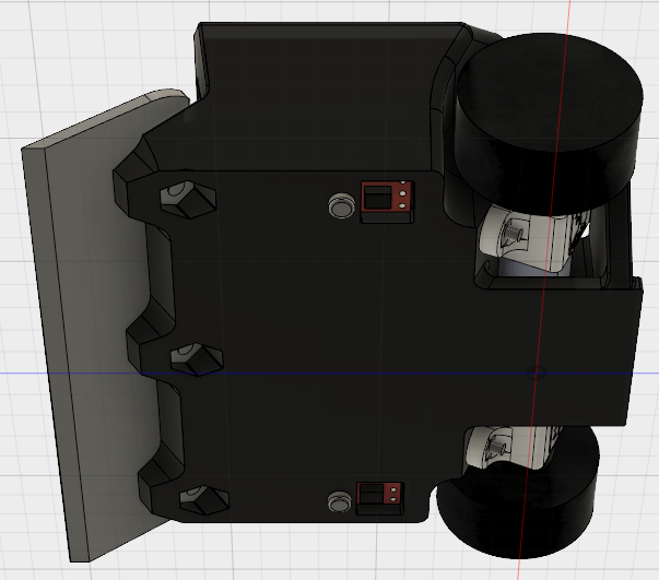
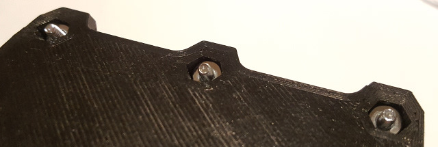
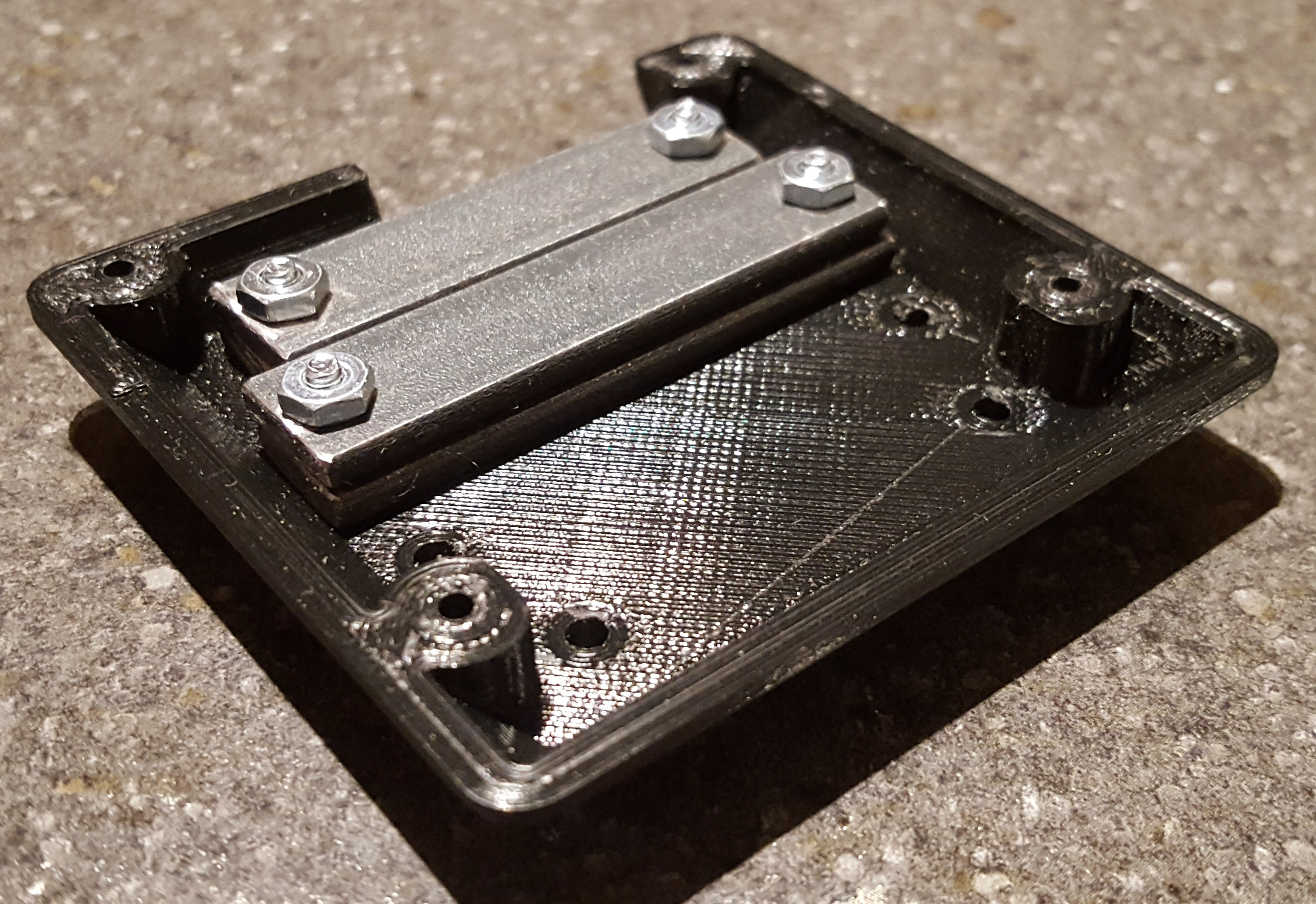
View from below showing the blade attachment nuts, QTR-1RC Reflectance Sensors and angled motor brackets.

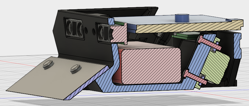
Section cut showing the angled motor bracket and battery snug fit.

I selected the Sharp IR sensors as primary sensors to locate the opponent because I already had four available and because they seemed to work well on @kevin’s Roku mini-sumo. I selected the A-Star 32U4 Robot Controller LV for the simplicity of having one single board with everything I need and also because I have experience with it. I had the objective of having the A-Star controller on the top so I could use the buttons and leds as user interface. I positioned the motor brackets at an angle to saves axial space, allowing me to fit the battery at the bottom of the chassis, keeping the A-Star on top and the overall height low. The angle also allows direct line of sight to the bolt holes allowing the use of a drill to finish the diameter after 3D printing and screwdriver access to tighten the screws. I positionned the MinIMU-9 v5 Inertia Measurement Unit in the space available below the A-Star and as close as possible to the axis of the motors. Finally, I positionned one QTR-1RC Reflectance Sensors in front of each wheel for ring border detection. As this is my first mini-sumo robot, I wanted to keep sensors to a minimum and have simpler code.

With all the components at their approximate position, I modeled the chassis around them providing mounting points for each component. I designed the external shape with angled surfaces as a “stealth” feature to divert the reflection of the opponent’s IR sensors either downward or upward. There is no “cover” but the edge of the chassis is higher than the components of the A-Star to protect it in case the robot rolls over. I may add one later using standoffs at the A-Star attachment points.

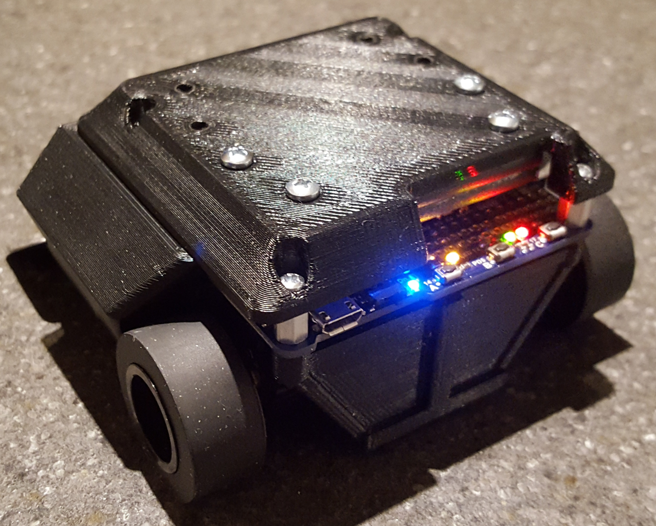
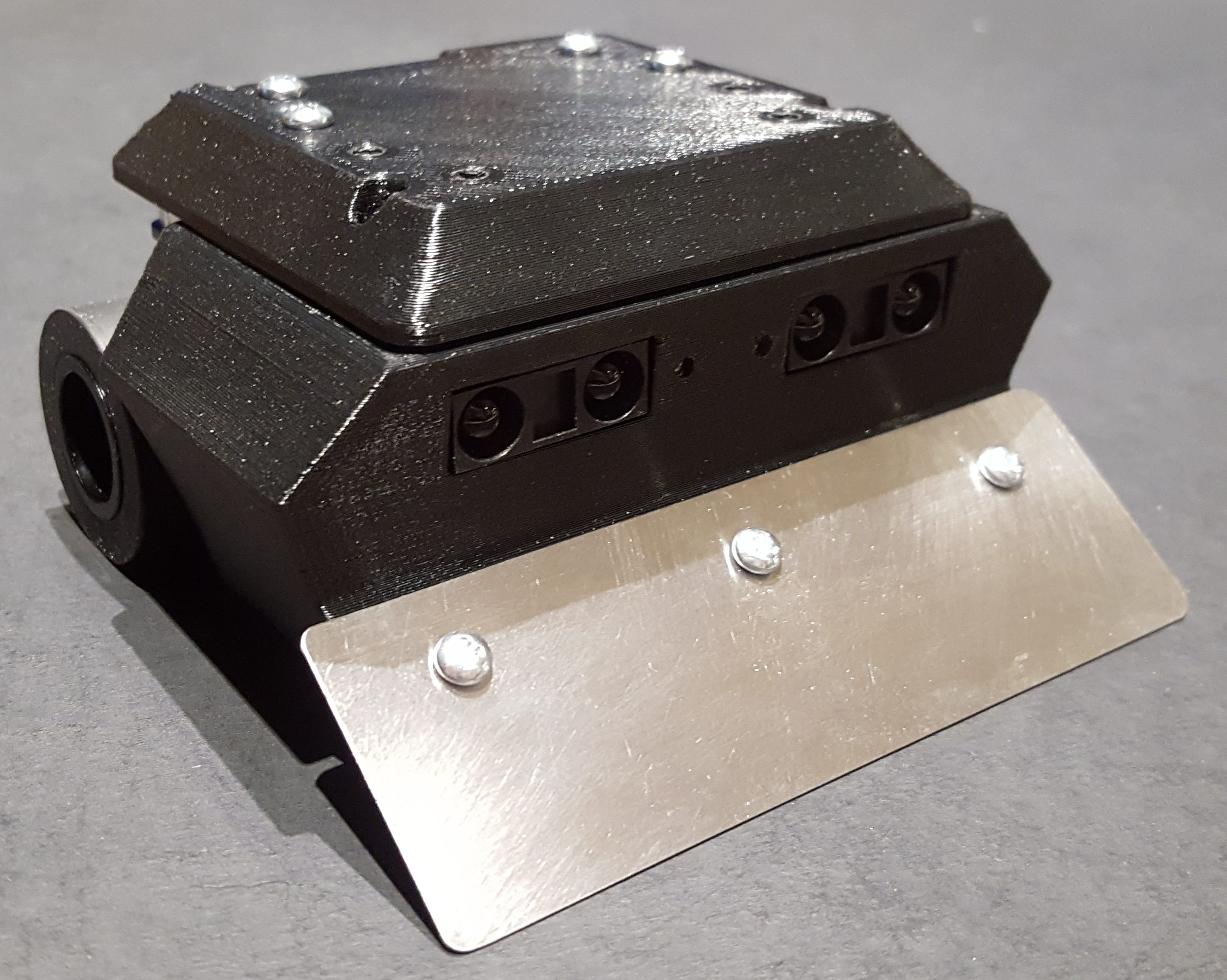
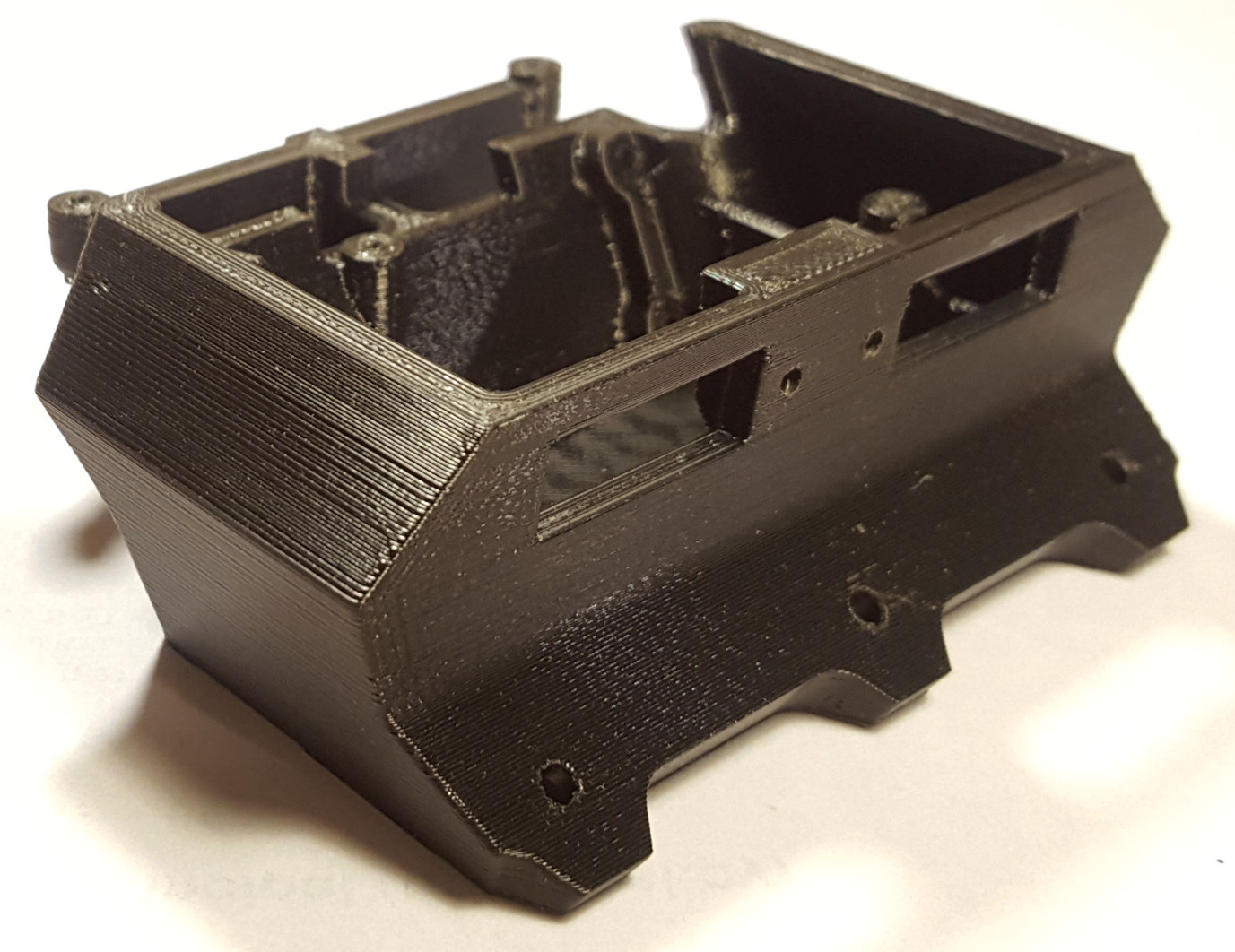
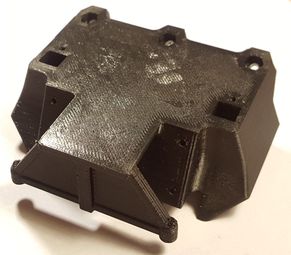
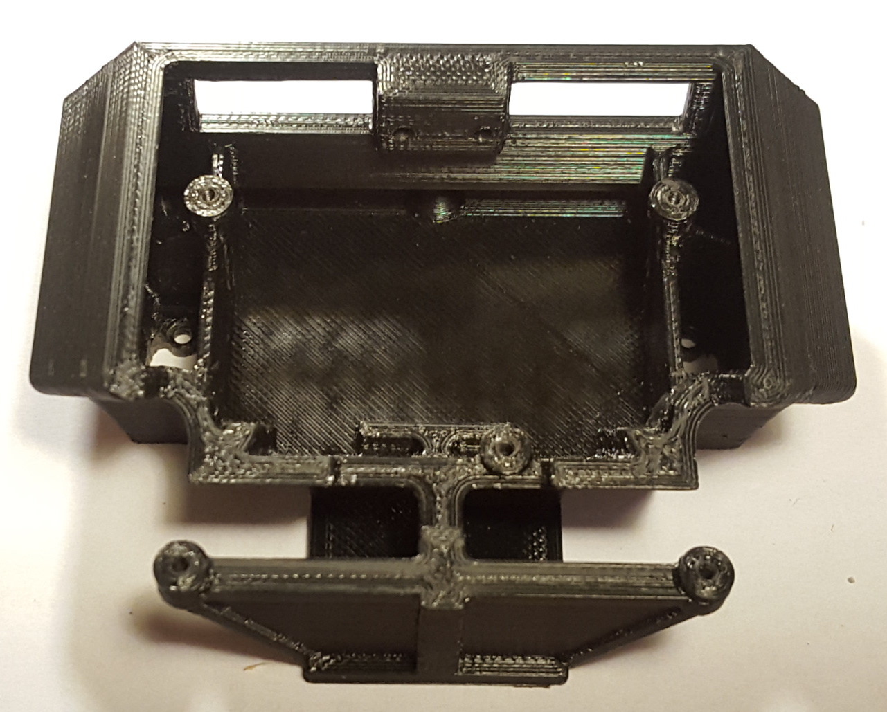
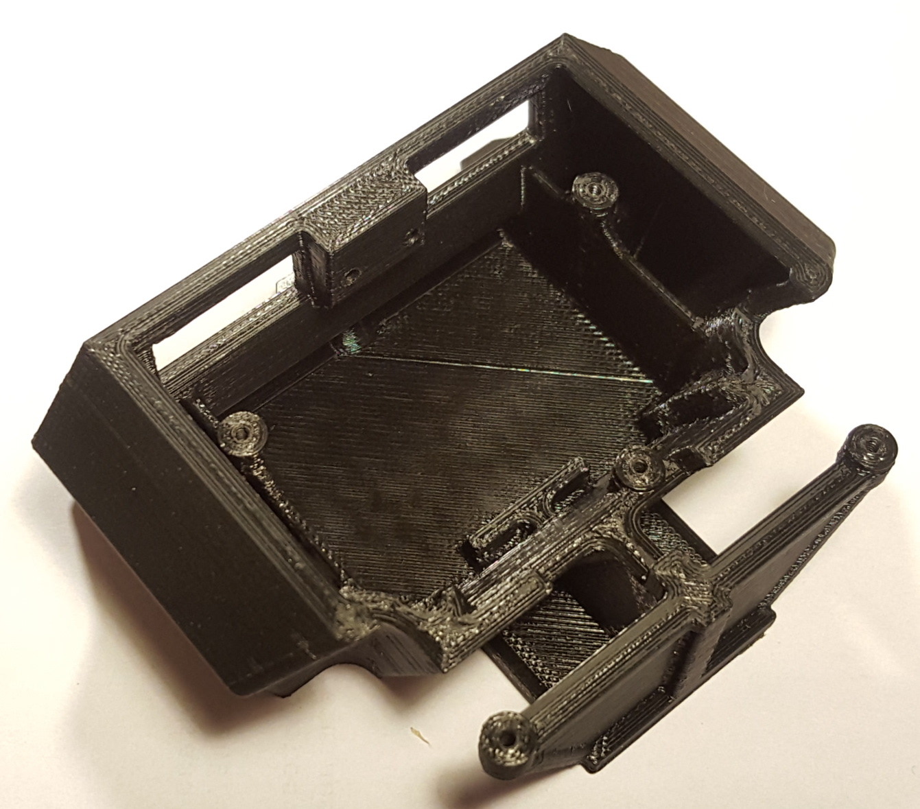
I got a first prototype chassis printed from a local source on 3D Hubs (pictures below). To my relief, all the components fit nicely inside the chassis except for a small ajustment I needed to make with a Dremel to clear small surface mount components near the bolt holes of the QTR sensors. Once I complete the assembly of the first prototype and am satisfied with it, I will update the 3D model and have the second chassis printed. I will also make the 3D model public at that time for anyone who would be interested in building one.

That’s it for now, I’ll post more as the build progresses.

3 Likes

Hi, DrGFreeman.

Thanks for sharing your project with us. We are really excited and can’t wait to see how your sumo robot turns out!

- Amanda

1 Like

Some pictures from the tial fit:

Motors & wheels, battery and Sharp IR sensors. No issue so far…

The QTR sensors are installed in a hard to reach area inside the chassis. A bit of goop glue to keep the nut on the PCB and a lot of patience got reason of it. The pictures shows the cutouts I had to make with a Dremel to clear the two surface mounted resistors. I will implement these in the 3D model for the next print.

With the A-Star 32U4 robot controller installed.

I still have to make the blade but I tried the nuts and they fit perfectly into the recessed hex shaped pockets. I was afraid the print would come out either too thight or too loose around the nuts.

It currently weight in at 185 grams without the blade, wires and IMU. There are deep pockets in the chassis on each side of the battery that I can fill with small lead pieces but the final weight will likely remain quite light.

Next step: the wiring…

1 Like

I completed the wiring and blade over last weekend and started some basic coding this week.

To save on space, all four sensors and the IMU are wired directly to the A-Star board without connectors. The direct soldering and short wires made the soldering somewhat challenging but not unfeasible. I kept the connector on the battery but shortened the leads again to save some space.

I made the blade out of a 2$ stainless steel ruler, like the type with a cork backing, except this one has a synthetic foam backing instead. I brushed the surface with a scotchbrite to remove the graduations markings from the ruler.

I will likely make some sort of cover to mount on top of the A-Star with1/4" standoffs. This will improve the looks by hiding the battery charge and balance connectors.

After checking the motors and sensors were all working well, I started coding some basic functions like border detection and opponent tracking. For the opponent tracking, I use a PID controller that works with the difference between the distance returned by the two Sharp IR sensors as input variable and sets the turn rate (difference between motors speeds) to face the opponent (difference between distance readings = 0). There is still some tuning to be made but the PID seems to work quite well already.

As you can see in the video below, this small robot already shows an aggressive temper…

Note that the sumo ring is smaller than normal, I made this one quickly out of cardboard until I make a regular size one out of MDF.

Next steps: Make cover, add weight and develop the code.

2 Likes

My chassis 3D model is now available on Thingiverse. It includes the latest modifications as well as some build notes about finishing the 3D print and fastners used.

2 Likes

Hi, @DrGFreeman.

We posted about your Mini Sumo robot on the Pololu blog! Thanks for sharing all of the details about your project; it looks great.

Your links to the MinIMU-9 v5 Inertial Measurement Unit in your first post and on Thingiverse go to the Sharp distance sensor (https://www.pololu.com/product/2474) instead of the MinIMU (https://www.pololu.com/product/2738). Also, it looks like you used some of our gearmotor brackets, so it might be nice to mention that for people who want to recreate your robot.

Thanks for taking the time to share your project, and I look forward to seeing more with this project or your others.

Ryan

1 Like

Wow! Thanks @ryantm, It’s an honor to be featured on the Pololu blog!

Good catch about the incorrect links. I corrected them here and on Thingiverse and added mention of the gearmotor brackets.

Now back to painting that “official size” sumo ring!

My Mini-Sumo now has a new 3D printed cover hiding the unsightly battery connectors. I replaced the #2-56 screws holding the A-Star to the chassis with #2-56 x 1/4" aluminum standoffs.The cover mounts on the standoffs and is easily removed by undoing the four screws. The interference fit of the stand-off threads in the chassis ensures they do not turn when undoing the cover screws. I designed an opening at the back of the cover to maintain access to the switches and LEDs on the A-Star used as user interface. Like the chassis, the cover features angled sides to divert the opponent’s IR sensors light.

The cover doubles as a holder for counter-weights. It has four pair of holes allowing installation of up to eight steel bars (1/2" x 1/8" cross-section) to adjust the weight and CG position, allowing control of the weight distribution between the wheels and blade.

I started with four steel bars at the rear-most mounting positions. This increases the robot weight to ~285g with approximately 75% of the weight on the wheels (see below). Experimentation will tell what is the ideal weight distribution.

I added the cover 3D model and build notes to the robot’s Thingiverse page.

1 Like

The cover looks great! We especially like the cut-out for the buttons (it looks like the power switch is still accessible from the underside of the cover) and the hidden weights. Let us know how the weight distribution experiment goes!

- Amanda

Can you upload de cover design again?, Im trying to do a similar design but with arduino UNO