We have made a sample 3pi robot “wall follower” project that shows an easy way to expand the capabilities of the 3pi. With just two Sharp distance sensors and minimal soldering, your 3pi can explore a room by following the walls and avoiding obstacles!
This wall follower was my entry in the LVBots Challenge 4.5 in the pool racing competition. Pool racing is an event where the entrants simultaneously race around and irregularly shaped object like the picture below. The first robot to complete 3 laps is the winner. My wall follower entry, named “Speed Racer,” took first place while racing against some rivals more than five times its size.
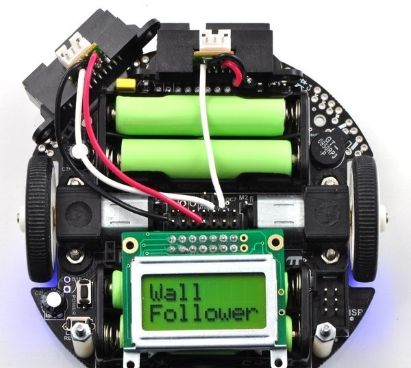
Here you can see the 3pi wall follower fully assembled:
What is “correct” way to mount side sensor? Horizontal, connector up or down? Or vertically, connector left or right? The datasheet doesn’t address this very well. It shows it mounted vertically, but I think is a basic generic description showing how the sensor works. I’m going to use the hole at left rear with a nylon spacer and fabricated right angle bracket, so I could mount the sensor in any configuration.
I suggest you pick the mounting orientation that’s most convenient for you as I’ve never noticed a significant difference between its horizontally mounted and vertically mounted performance. The datasheet does mention two ways in which mounting orientation can improve distance-measuring accuracy, however. One has to do with measuring the distance to a surface with a boundary line that separates two drastically different regions (i.e. an abrupt change in color or material), and the other has to do with measuring distances to an object that is moving relative to the sensor. Mounting your sensor vertically might give you the most accuracy for an application like the 3pi wall-follower, but I have no real sense of how much performance improves by mounting in their suggested orientation in these cases.
I need some bumper material. Sometimes the 3pi slams into rear or front wall rather hard, not doing evasive action very well. Need suggestion for a shock absorber material that I could somehow apply to front and back edges of platform PCB. I guess a bit of foam would work. Any other ideas?
donde
I’m a fan of adhesive backed weather stripping as a general robot bumper/padding/gripping material (variety of shapes/sizes, plus you can get it at most hardware stores).
Very good Adam. I’ll check it out. Another thought I just had is slicing up a “Magic Rub” artist eraser. They are pliable, but no built-in adhesive like you mention using weather stripping material.
donde
Is there a way to get front (and bottom) LEDs to sequentially flash? The main while loop has a lot to do. Doing this LED routine would really slow the wall-follower down.
donde
I’m not sure I understand what you’re asking. Are you saying you want the two user LEDs to alternately flash but you don’t know how to do it without burdening the processor too much?
Ben,
I figure with a delay of 200 ms or so to flash the LEDs, within the main while loop would slow the 3pi too much, or do I have wrong thinking again?
donde
Using loop delays to blink the LEDs would be a bad idea, but you can easily do it using timer-triggered events in your main loop.
For example:
int main()
{
  while (1)  // main loop
  {
    if (get_ms() % 400)
    {
      red_led(1);
      green_led(0);
    }
    else if (get_ms() %200)
    {
      red_led(0);
      green_led(1);
    }

    // the rest of your main loop code
  }

  return 0;
}
Ben,
Thanks so much. I should have noticed the part of wall-follower code that backs up every 15 seconds for 1 second, using modulo arithmetic and the timer. About how fast does an average instruction execute?
donde
Most AVR instructions take one or two clock cycles (you can look at the AVR instruction set to see how many cycles each instruction takes, and the list file generated when you compile your code shows you the assembly instructions in a way that’s really easy to follow), which means typically 50 to 100 ns per instruction.
Ben,
Well, tried the code you suggested, but didn’t work. I think it’s because the other modulo to back up every 15 seconds is running also. Spent quite a bit of time trying. Wound up just making both LEDs light at same time when backing. Still like to flash LEDs alternately and do backup routine. More focus, I guess.
donde
Here is the code that worked for me to flash LEDs alternatively every 0.5 seconds.
donde
 // This is the "main loop" - it will run forever.
        while(1)
        {
		if (get_ms() % 1000 < 500)
		{
			red_led(1);
			green_led(0);
		}
		else if (get_ms() % 1000 > 500)
		{
			red_led(0);
			green_led(1);
		}
// The rest of while loop
       }
}