Need Help with Gyro Drift using Magnetometer

Hi guys,
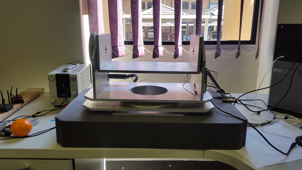
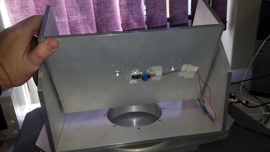
I’m busy with a Stabilized Pan and Tilt platform project that will carry a mid-sized camera. The idea is to eliminate all unwanted external movements only in the Pitch and Yaw axis while aiming at a specific target. I am using the following electrical components:
• Arduino UNO R3
• Pololu Dual VNH5019 Motor Driver Shield for the Arduino that powers 2x Pololu Metal Gearmotor 75:1 with a 48 CPR Encoder.
• MiniIMU-9 v2
In my current program I am using the X-axis Gyro sensor for the Tilt-axis and the Y-axis Accelerometer to prevent Gyro drift, but in my Pan-axis I’m only using the Z-axis Gyro sensor whereas I would like to use the Magnetometer to prevent Gyro drift. My problem is that I do not know how to use the Magnetometer readings in my current program to prevent this Gyro drift.
I calibrated the LSM303 sensor as stated in the library, ran the Heading program and it seems to be working. I’ve even ran the AHRS program on Arduino and Python and it seems to be working. I have gone through some examples how the LSM303 where used in other applications but I’m still clueless in how to use the Magnetometer in my program.
I have added my current program for you all to look at. I am quite new in programming so please excuse my programming methods.

#include <PID_v1.h>
#include <Wire.h>
#include <L3G.h>
#include <LSM303.h>
#include <DualVNH5019MotorShield.h>

LSM303 compass;
L3G gyro;
DualVNH5019MotorShield md;
String MyVar("");


//----------------------------------------------------------------//
double SetpointT, InputT, OutputT; //Define Variables we'll be connecting to
double KpT=22.0, KiT=500.0, KdT=0.07;
PID myPIDT (&InputT, &OutputT, &SetpointT,KpT,KiT,KdT, DIRECT); //Specify the links and initial tuning parameters for the TILT axis
//----------------------------------------------------------------//
double SetpointP, InputP, OutputP; 
double KpP=13.0, KiP=100.0, KdP=0.05;
PID myPIDP (&InputP, &OutputP, &SetpointP,KpP,KiP,KdP, DIRECT); //Specify the links and initial tuning parameters for the PAN axis

int setspeedPAN;
int setspeedTILT;

#define RAD_to_DEG 57.295779513082320876798154814105
float accXangle = 0;
float R = 0;

const int sampleRate = 1;  //Variable that determines how fast the PID loop will run

void updatevars()
{
    int rchar;   // = Serial.read();
    
    if (Serial.available() > 0) 
    {
      rchar = Serial.read();

      if(rchar == 'p')
      {
        KpT = MyVar.toInt();
        myPIDT.SetTunings(KpT, KiT, KdT);
        Serial.print("Kp Tilt=");
        Serial.println(KpT);
        MyVar = "";
      }
      else if(rchar == 'i')
      {
        KiT = MyVar.toInt();
        myPIDT.SetTunings(KpT, KiT, KdT);
        Serial.print("Ki Tilt=");
        Serial.println(KiT);
        MyVar = "";
      }
      else if(rchar == 'd')
      {
        KdT = (MyVar.toInt()/100.0);
        myPIDT.SetTunings(KpT, KiT, KdT);
        Serial.print("Kd Tilt=");
        Serial.println(KdT);
        MyVar = "";
      }
     else if(rchar == 'a'){
        KpP = MyVar.toInt();
        myPIDP.SetTunings(KpP, KiP, KdP);
        Serial.print("Kp Pan=");
        Serial.println(KpP);
        MyVar = "";
      }
      else if(rchar == 'b')
      {
        KiP = MyVar.toInt();
        myPIDP.SetTunings(KpP, KiP, KdP);
        Serial.print("Ki Pan=");
        Serial.println(KiP);
        MyVar = "";
      }
      else if(rchar == 'c')
      {
        KdP = (MyVar.toInt()/100.0);
        myPIDP.SetTunings(KpP, KiP, KdP);
        Serial.print("Kd Pan=");
        Serial.println(KdP);
        MyVar = "";
      }
     
      else
      {
        MyVar += char(rchar);
      }
   }
}

void stopIfFault()
{
  if (md.getM1Fault())
  {
    Serial.println("M1 fault");
    while(1);
  }
  if (md.getM2Fault())
  {
    Serial.println("M2 fault");
    while(1);
  }
}

void setup()
{
  Serial.begin(9600);
  Wire.begin();
  compass.init();
  md.init();
  compass.enableDefault();
  
  compass.read();
  R=sqrt(pow(compass.a.x,2)+pow(compass.a.y,2)+pow(compass.a.z,2));
  accXangle = acos(compass.a.y/R)*RAD_to_DEG - 91;
  
  InputT = ((gyro.g.x/256)-1.6)+(accXangle);
  SetpointT = 0;
  InputP = ((gyro.g.z/256)+0.9)+((gyro.g.y/256)-1.0);
  SetpointP = 0;

  if (!gyro.init())
  {
    Serial.println("Failed to autodetect gyro type!");
    while (1);
  }
 
  compass.read();
  myPIDT.SetOutputLimits(-400, 400);
  myPIDP.SetOutputLimits(-400, 400);
  
  gyro.enableDefault();
  
  myPIDT.SetMode(AUTOMATIC); //Turn on PID - Tilt
  myPIDT.SetSampleTime(sampleRate); //Sets the sample rate
  
  myPIDP.SetMode(AUTOMATIC); //Turn on PID - Pan
  myPIDP.SetSampleTime(sampleRate); //Sets the sample rate
}

void loop()
{
  gyro.read();
  compass.read();
  R=sqrt(pow(compass.a.x,2)+pow(compass.a.y,2)+pow(compass.a.z,2));
  accXangle = acos(compass.a.y/R)*RAD_to_DEG - 91;
  
  InputT = ((gyro.g.x/256)-1.6)+(accXangle);
  SetpointT = 0;
  myPIDT.Compute();
  
  InputP = ((gyro.g.z/256)+0.9)+((gyro.g.y/256)-1.0);
  SetpointP = 0;
  myPIDP.Compute();
  
  md.setM1Speed(OutputT);
  md.setM2Speed(OutputP);

  updatevars();
 
}

Thanks

Hello.

In a similar way to how you use the gravity vector to compensate for drift in your tilt axis, you can use the orientation vector from the compass as a reference to compensate for drift in your pan axis. You can take a look at some of the other AHRS implementations listed on the Resources tab of the MinIMU’s product page for more examples of how to do that.

-Jon

Hi Jonathan!

Thank you for your reply. Since then I have tried to apply your suggested method in my current program and had some success, but I’m now battling with inaccurate direction readings from the compass as well as fluctuating output readings. I have change some components as well. The hardware I’m currently using now is as follows:

  • Arduino MEGA ADK
  • Escon 36/2 DC Maxon Motor driver
  • 22DCL Maxon Motor with an ENX16 EASY 256IMP Encoder and 83:1 gearhead.

I have attached a picture of my current platform I’m trying to stabilize. The structure is made of Aluminium (as you can see), and I have located the IMU below the Tilt-Platform.
I understand that the Aluminium structure as well as the motors has an effect on the magnetic flux readings of the compass sensor, but unfortunately I have to work with what I have currently.

  1. I have done a few compass calibrations before testing( which you can see is quite difficult to do when the IMU is still attached to the platform), but I still notice that when I rotate the Pan-Platform to 90deg, and then to 270deg, the platform direction differs with about 20-25deg, leaving my platform completely inaccurate.
    a) Am I doing something wrong with the calibration procedure?
    b) Is the IMU located at the correct position?

  2. After calibration, I still receive the fluctuating output values even though the platform is at complete stand-still ( some jump up to ±9deg). And this obviously causes my platform to oscillate around the desired direction of interest. :cry:
    a) Is this due to the Aluminium structure of the platform or/and the servo motors causing this fluctuations?
    b) Should I be looking into other methods instead of using the compass sensor?
    c) Is it my program that has to be revised?

I have attached my recent code as well. This code only tests the compass and gyro-sensors around the Pan-axis.

[code]#include <Wire.h>
#include <LSM303.h>
#include <L3G.h>
#include <PID_v1.h>

LSM303 compass;
L3G gyro;

double prevCompass, setpCompass;
double Sigma;

double compOutput;
double MAG_Kp=2.0, MAG_Ki=1.0, MAG_Kd=1.0;
double InputP, OutputP, SetpointP;
double Kp_PAN=1.0, Ki_PAN=0.0, Kd_PAN=0.0;
PID PIDpan (&InputP, &OutputP, &SetpointP,Kp_PAN,Ki_PAN,Kd_PAN, DIRECT); //Specify the links and initial tuning parameters for the PAN axis

const int sampleRate = 1; //Variable that determines how fast the PID loop will run

int PIN_DIRECTION_0 = 5; // Direction Pin for Motor 1 (NOT BEING USED AT THE MOMENT)
int PIN_ENABLE_0 = 6; //Enable Pin for Motor 1 (NOT BEING USED AT THE MOMENT)
int PIN_PWM_0 = 2; //PWM Pin for Motor 1 (NOT BEING USED AT THE MOMENT)
int PIN_DIRECTION_1 = 11; // Direction Pin for Motor 2
int PIN_ENABLE_1 = 10; //Enable Pin for Motor 2
int PIN_PWM_1 = 8; //PWM Pin for Motor 2

void setMspeed(int M, int V1) //Set speed function for the motor driver
{
int direct=0;
int a;

if (V1 < 0)
{
  direct = 1;
  V1 = -V1;
}
if (V1 > 200)
{
  V1 = 200;
}

a = V1 + 26;
if(M == 0)
{
  analogWrite(PIN_PWM_0, a);
  digitalWrite(PIN_DIRECTION_0, direct);
}
else
{
  analogWrite(PIN_PWM_1, a);
  digitalWrite(PIN_DIRECTION_1, direct);
}

}

void setM1speed(int v) ////NOT BEING USED AT THE MOMENT
{
setMspeed(0,v);
}
void setM2speed(int v)
{
setMspeed(1,v);
}

void setup()
{
Serial.begin(9600);
Wire.begin();
compass.init();
compass.enableDefault();

pinMode(PIN_DIRECTION_1, OUTPUT);
pinMode(PIN_ENABLE_1, OUTPUT);
pinMode(PIN_PWM_1, OUTPUT);
digitalWrite(PIN_ENABLE_1, HIGH);

compass.m_min = (LSM303::vector<int16_t>){-452, -377, -199}; //compass calibration neg
compass.m_max = (LSM303::vector<int16_t>){+106, +379, +453}; //compass calibration pos

PIDpan.SetOutputLimits(-200, 200);
PIDpan.SetMode(AUTOMATIC);

delay(2000); // time for compass sensor to recieve an accurate set point position.
compass.read();
setpCompass = compass.heading();
prevCompass = setpCompass;
}

void loop()
{
double compChange;
double compassNow;
float Delta;
float dirxError;

compass.read();
compassNow = compass.heading();

compChange = (compassNow - prevCompass);
Delta = compChange;

dirxError = (compassNow - setpCompass);
if(dirxError >= 180)
 {
   dirxError -= 360;
 }
 else if(dirxError <= -180)
 {
   dirxError += 360;
 }

Sigma = (Sigma + dirxError);
Sigma = Sigma < -200 ? -200 : Sigma >= 200 ? 200 : Sigma; //limit range
compOutput = (Sigma * MAG_Ki) + (Delta * MAG_Kd) + (dirxError * MAG_Kp);

SetpointP = compOutput;
InputP = 0.0; // (((gyro.g.z/256)+0.9)+((gyro.g.y/256)-0.8));
PIDpan.Compute();

setM2speed(OutputP);

prevCompass = compassNow;

/*
Serial.print(OutputP);
Serial.print("\t dirxError: “);
Serial.print(dirxError);
Serial.print(”\t Compass Setpoint: “);
Serial.print(setpCompass);
Serial.print(”\t Compass Output: “);
Serial.print(compOutput);
Serial.print(”\t Compass Now: ");
Serial.println(compassNow);
//*/

}[/code]

I am hopelessly lost!
Thank you for your time and effort so far!! (Please excuse my English and my use in punctuation. English is not my first language :blush: )

-Vince-

Magnetometers are extremely sensitive and need to be calibrated in the environment in which they will be used. Current carrying conductors, iron objects and magnets (as in motors or servos) will cause great confusion. That is a likely source of trouble in your case. Mount the magnetometer as far from motors and wires as you are able, and calibrate in place.

Thanks for the reply Jim. I had a feeling that this is the problem. I’ll have to relocate the IMU until the fluctuation reading of the compass decrease.
Otherwise, I thought of using the quad encoder on one of the motors instead of the compass to reduce the gyro drift…

No, wait, that wont help me at all. I’ll only end up with a platform that wont compensate for any external movements in the Pan axis…
I’ll just have to relocate the IMU then. Meanwhile, can you please tell me how I can retrieve the raw data from the LSM303DLHC sensor?

Thanks!

[quote]Meanwhile, can you please tell me how I can retrieve the raw data from the LSM303DLHC sensor?[/quote]Pololu provides a very simple example program for that, but the library you’ve included may have a function to return raw readings as well. This example for the DLM may have some slight differences in register locations: pololu.com/file/0J537/LSM30 … e-code.zip