My Zumo build

Here’s the skinny on my Zumo build:

From the bottom:

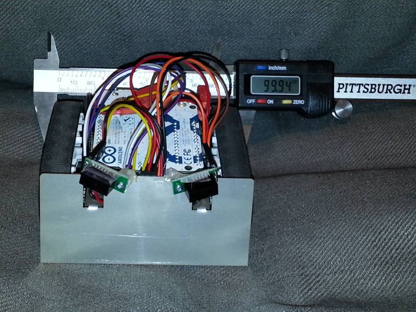
You can see that I Dremeled out a space for the too-long LiPo battery pack, but even so, the motors are actually a smidgen too close together to fit the pack between them. The battery pack sticks out in the back.

The red strip is the 6-sensor part of the QTR-8RC. I was going to machine some mounts to screw them into the blade, but events have conspired against me (latest: brakes on my care broke down today!) so I gave up and used hot glue “for now” (yeah, that’s what I tell myself everytime :wink:

Here’s from the front:

The sensors are 10cm Sharp presence sensors. They can be used to either hug walls in navigation (slow down the tread opposed to the sensor which detects something) or to turn/ram into opponents for Sumo. It is kind-of near-sighted, though :slight_smile:
Again, I had been designing a simple mount to screw the sensors into, but gave up and hot glued the screws. Hot glue does not stick very well to stainless, unless you really rough it up before, which I haven’t. Yet?
You also see the Scotch tape across the back of the sensors. This is to avoid the back of the sensor boards shorting out on the shield or other metal. Learned this the hard way :slight_smile:

Right behind/below the sensors, you can see red and black wiring. That’s actually the wires for the motors. I pulled them up in front of the board and attached them to 90-degree headers on the shield, to be able to easily disconnect them and disassemble the robot again.

From the side:

Those silicone treads are dust magnets in my house, what with kids and cats and dogs and stuff.

You can also see that the LiPo pack is slightly too long – that’s actually just the wires and wrapping that protrudes beyond 100 mm, so it could be squished into a 100x100 millimeter cube. If this was designed, though, I’d go with a 900 mAh pack that probably would fit within the battery compartment, no Dremeling needed.

The red connectors are Deans-knockoff nylon-housed high-power connectors, which I use for all my batteries/motors. A little overkill, but so far, I have weight to spare if I’m designing to the 100mm division. I’ll probably have to add some steel bar on the inside of that battery compartment to make it heavier and stickier :slight_smile:

The extra connector is for charging, and the LiPo balancing wire can be seen tucked in behind the unused USB port on the Arduino.

The rat’s nest of cabling on top is 6" pre-crimped female/female wiring connecting the sensors and the shield. I soldered extra male headers on the outside of the Arduino hook-up pins, which gives me access to all the signals both for sensors, and for debugging.

Right now, I’m not using A3, and also not using A4/A5 because I have nothing with I2C right now (not currently using the compass/accelerometer.) Possible future improvements include using the accelerometer to detect permanent angling (loss.) I could also use a second AVR controller with a LCD display and a few buttons to add a detachable configuration/debug UI over I2C.

Not visible, but also a mod: I de-soldered the R10 resistor from the shield, turning the 3:2 voltage divider into a 2:1 divider, which allows me to monitor the full range of the LiPo cell voltage. When the voltage goes below 6.55V, I make it stop the motors and start beeping like an alarm clock buzzer, to avoid draining down to 6.4V. It goes out of alarm mode if voltage recovers above 6.8V. I need a fair bit of hysteresis, because stopping the motors will make the voltage recover somewhat by itself.

Thanks for sharing! It’s always nice to see what people are doing with the Zumo. Are you going to enter a sumo competition? Let us know if you get any cool videos of this in action. --David

Actually, my main thought is to use it as target practice for my Mech Warfare build :slight_smile:

But if there’s a friendly hobby sumo event somewhere around here (SF bay area,) it’d totally be worth it to change the firmware and meet some fellow robot enthusiasts for an evening.

This is a well-established and active group - you can see they have monthly
activities. There may be other groups too.

hbrobotics.org

Also, in San Mateo in April is the big event on the west coast. I’m sure they’d
love to see some Zumos in the Sumo events. You have several months to get
yours into battle condition.

robogames.net

So far, so good, on my own Zumo build. All in all, I give the platform
design a grade of A, :).

It was easy enough to put together, although I did manage to destroy the
acrylic 2-piece spacer in the process. So I went to the 1-piece spacer,
with use of a couple of thin washers to raise the Zumo shield so the solder
connections wouldn’t clash. I was just glad I didn’t break the inserts holding
the motors.

The only thing I’m a little worried about are the plastic braces that hold
the idler wheels. I think those could be beefed up a bit, with maybe 50%
thicker plastic on top, and with the sides beveled out at a more oblique
angle to ease the strain on the current 90-deg bends.

One question - in the first sketch I wrote [am using Duemilanove chip], I
wrote my own motor driver using the std PWM [500 Hz, I believe]. I found
that, once the motor starting getting up to speed, the entire Zumo shield
would completely cut-out [power interruptus]. This only happened when
the Zumo was on the floor, so under motor loading. With the platform up
on blocks, it ran ok.

After I found the ZumoMotor library, which uses 20 Khz PWM, all goes ok
so far. So, I am wondering what’s the deal with the lower PWM frequency.
Motors are too inefficient? H-bridge overload? ???

All in all, pretty happy, so far.

I’m already signing up for another event (or two) there though – there’s only so much time :slight_smile:

I’ll post pictures of those projects, too, when they get closer.

I’ve run with three different PWM frequencies, and all of them work. The only time it didn’t work for me, was when I used anti-EMI capacitors on the motor in addition to the ones already on the shield. Removing those made it work.
I’m using the “high power” version of the micro gear motors, too.
However, I am feeding it with a high-current LiPo battery. If you don’t have fresh batteries, or your batteries are not good at delivering high currents, then you might get too much voltage drop for the system to run well, perhaps?

I’m using the higher powered 100:1 motors, and 2500 mA-hr NiMh AA-cells.
I’ve used such batteries to power my walker with 12 RC servos, so they
can provide pretty good current. I did not install extra caps on the motors.
I’m waiting to hear from the Pololu people about this [ie waiting on a forum reply]. I suspect this whole system is a little finely-tuned.

FWIW, the section of the 2-piece spacer over the motors has those large
and seemingly useless [at least to me] cutouts, and the rims of which are
only 1/16" wide, so very flimsy.

b.pololu-files.com/picture/0J414 … 4865e9a70b

Hello.

When you say that the entire Zumo shield would cut out, do you mean that the Arduino browned out and reset, or just that the motors would stop? Do you have access to an oscilloscope you could use to look at what’s happening to the battery voltage when it cuts out?

- Ben

Those holes are there so that you can solder things to the Arduino headers and parallel expansion strips.

- Ben

Actually, I slightly misstated the problem [bad dog]. Somehow I blew both
Leds on the left rear of the Zumo shield, so none of the 4 were lighting
yesterday. Today, soldered in a new Led, so the 3 in the Vin chain are
working now.

With the bad sketch [500 Hz PWM], both the Arduino resets as signalled by
led13 going out, and the motors stop dead on the spot, but the Zumo shield
keeps power - ie, the Vin Led chain stays lit. There may be momentary
power interruptus in the Zumo shield, however. Offhand, do you know
how quickly the boost regulator clicks on after power application?

Unfortunately, I can’t really tell what’s going on, because it only happens
when running on the floor, and it won’t seem to happen if I simply push
on the tracks to add load down the motors, or bang on the bottom of the
robot, and cannot attach a scope to the running bot very well, so ???
Doesn’t seem to be due to possible loose batteries or connections.

OTOH, I now have an XBee module working on the Arduino bd, so maybe
I can write a sketch to monitor some critical info.

In any case, it doesn’t seem to happen when running the ZumoMotor sketch
using 20 Khz PWM.

Yeah, I was probably a little too rough and managed to fracture the cutout
area. The rim is a little narrow around that cutout, and some of us suffer
the bane of heavy hands.

b.pololu-files.com/picture/0J414 … 4865e9a70b

Hi, danm3030.

Are you still running into problems? Have you managed to narrow down the cause? I’m not sure why you’re seeing the behavior you do, since I’m fairly sure we’ve used Arduino’s analogWrite(), which generates 490 Hz PWM, to control the motors without any trouble.

It seems strange that your problem only happens on the floor and not when you load down the motors manually. Does it happen consistently everywhere, or only on a certain type of surface?

Also, this might seem obvious, but did you make sure your batteries are well-charged?

- Kevin

Hi Kevin, am still having the same problem, although spending most time
doing many other things. I did get the XBee link going, and figured the
problem occurs only when the motors are going wide open, near full duty-
cycle. The Arduino resets, but the Zumo shield Leds don’t blink perceptibly.

I still cannot repeat it, except on the floor - this is hard flooring and not
carpet. I can almost stall the tracks by hand and bang on and shake the
platform, but it never crashes that way. I also tried rubbing my feet on
the carpet, and touching the pads on the Arduino board, but this won’t
crash it either. So, probably not due to excess motor [stall] currents or
ESD.

Also, it doesn’t happen when the batteries are low - ie, everything worked
ok when the NiMH cells were down to 3.6V [almost dead], but does happen
with fully-charged batteries. IE, the motors can’t get up to full-speed with
low batteries. So, something to do with the motors going full-speed, but
not necessarily drawing close to stall currents, so ???. The only thing I can
think of is motor noise not being fully quenched by the 3.3nF caps.

In any case, I will start using only the ZumoMotor library in the future, and
watch if the problem ever occurs there.

BTW, the ZumoBuzzer library works good. Is that Bach’s Tocata and Fugue
in example #2?

Also, to make the connection to the buzzer driver, I used a 0.1 uF cap
instead of a hard wire. As I see it the buzzer is a magnetic device, and not
a piezo, and might fry if it gets a constant DC Level. No?

That buzzer looks piezo to me?

The danger with ESD for CMOS chips (almost all chips these days) is that they build up “burn-out” in the MOSFET devices, and once burned out, the devices fail. They do not usually come back. Thus, trying to force ESD “issues” is like hitting it with a little hammer, trying to force it to break… it probably won’t un-break if you succeed!

Maybe the problem is mechanical? Do any of the contacts on the underside touch the motors, or one of the batteries, when it’s on the ground and running around? Do the motors vibrate and hit the board?
A piece of Scotch tape across all openenings, or the underside of the shield, may help isolate the problem. (Pun intended :wink:

If I fry the chips on my board, I can replace them, no smt. I was trying
to break it, :). Problem doesn’t seem to be mechanical, as I pounded
the case with my hand, and also shook it “very” hard, with the motor
running. Like I said, the only thing seems left is motor noise at high
RPMs, possibly the h-bridge kicking off, and resetting the system.

Re the buzzer, it measures about 30 ohm DC resistance, so likely to
be magnetic and not piezo. First thing I checked after seeing the
schematic.

I have the 1-piece acrylic spacer on the base, set off from the Zumo
shield by washers for spacers, so it’s not any electrical shorts. Plus
those would certainly show up when I shake the robot, not just
occurring at full speed ahead.

Hello.

That behavior sounds very strange; I would not expect the PWM frequency to have a very significant effect. I don’t suppose you have access to an oscilloscope? It would be nice to see what is happening to the battery voltage in the various cases. Do you have any other batteries you can try?

The buzzer on the Zumo is not piezo, and yes, leaving the buzzer pin high for an extended period of time would waste a lot of current and potentially damage the buzzer.

- Ben

Thanks! I should go check my code, because I don’t think I reset the PWM output to a particular state when I turn it off.

You might want to add a note about this in the shield instructions :wink:

Yeah, I mentioned before, I can’t really connect the oscilloscope
because the problem only shows up when the robot is running on
the floor near full-speed, and I cannot repeat the problem any other
way, although I have tried about everything I can think of - heavy
pressure on the treads, shaking the platform, high/low battery
charges, ESD.

I guess I can try alkaline AA-cells, rather that NiMH to see if that matters.
Got one or two other ideas to try too.

Run each of the treads in a different direction on the floor, so it stays in one place, and keep the leads connected :slight_smile:
You will get quite a twisted braid of cables pretty quickly that way, though, so perhaps alternate the spinning direction every second?