My Shutdown Circuit

Hi,

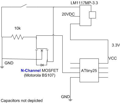
I have thought about a way to turn off an AVR and the entire circuit it is in. Finally, I came up with the test circuit attached.

Basically an n-channel (!) mosfet (sorry, I don’t have the appropriate symbol) is used to open the circuit when it shall be turned off. The gate is pulled down i.o.t. insure the circuit stays in off condition until the button is pressed, which switches on the AVR. Then the pin connected to the gate is made high active to keep the mosfet open. So when the button is released, the circuit is on until the gate-pin is made low active.
Note: I have one capacitor between each of the voltage regulator’s pins. These are not depicted however.

I tested it and it seems like it works fine. Since I am not an electrical engineer or well experienced I was hoping I could get some feedback on this circuit. Are there cases where I may have problems with it? Any improvements or things I have forgotten? Any better circuits?

Thanks, appreciate it!
-Robert

Hello,

That circuit might work for your application, but I do see a couple of potential issues. One is that in the off state, there is still a possible current path from 20V through the regulator and the AVR to ground. This might not actually conduct any current with the parts you are using now, but with another regulator or a different voltage source, it might not work. Instead, it would be safer to make the ground pin on the AVR connect to the same node as the ground pin of the regulator, so that the FET can disconnect the entire circuit. The other thing I’m worried about is that the pushbutton is required to conduct all of the current used by the circuit before the FET switches on, which could easily be more than 100mA if you have a few things connected to the 3.3V line. You could possibly fix that by having the switch control the gate of the FET instead of the ground line, but you’ll have to be careful not to put a voltage above 3.3V on the AVR pin.

I also noticed that you are above the maximum input voltage of 15V for the LM1117MP-3.3, so you could be damaging it. As you continue your tests, I recommend checking all of the voltages and currents on all of the parts with your expectations to make sure that everything is working the way you think it is. Do you have access to an oscilloscope?

For more general use, the Pololu Pushbutton Power Switch SV should do everything you want and work up to much higher currents, and it’s not dependent on the AVR for operation. However, I can understand the desire to do it yourself! By the way, can you tell us some more about your project? What do you need the shutoff feature for?

-Paul

Hi Paul,

thank you very much for your notes!!

“[…]One is that in the off state, there is still a possible current path from 20V through the regulator and the AVR to ground. […]”

–> That’s true and might be a real problem. Up to now I was using voltages below 10V (luckily considering my wrong assumption of 20V operating max of the volt. reg. …) and I noticed that almost the full voltage is seen by the AVR in the circuit. Obviously the resistance is high enough that it is not damaged in my circuit, but as you said, that might not work with a different circuit. When the circuit is in on state, the VCC is 3.3V as intended. Do you think the high voltage on the AVR can become a problem other than just switching it on?

“[…]Instead, it would be safer to make the ground pin on the AVR connect to the same node as the ground pin of the regulator, so that the FET can disconnect the entire circuit. […]”
–> That was my initial approach, but I recognized a voltage drop of about 1.8V over the mosfet (i.e. the ground pin of the regulator was 1.8V above the GND shown on the left of the figure. So if the AVR’s GND pin is connected to 1.8V, the lowest the AVR’s pins can deliver is 1.8V and thus the mosfet could not be turned off. Frankly, I haven’t fully understood the voltage drop of 1.8V…

“[…]I’m worried about is that the pushbutton is required to conduct all of the current used by the circuit before the FET switches on, which could easily be more than 100mA if you have a few things connected to the 3.3V line. You could possibly fix that by having the switch control the gate of the FET instead of the ground line, but you’ll have to be careful not to put a voltage above 3.3V on the AVR pin.[…]”

–>Thanks for the hint. You are definitely right, 100mA is not a whole lot. Would you say this is typically the limit for pushbuttons? Maybe I better control the gate by the button and just use a voltage divider to make sure the voltage on the pin is low enough.

Right now there are not a lot of components in the circuit. I will make the test circuit a little more representative, i.e. include some more realistic components, then test again. Yep, I do have an old oscilloscope…

Thanks for the hint with the pushbutton switch. Very interesting. I’ll keep that in mind.
Sorry, there is no real project to show. I am basically playing around with the AVR and trying to “explore” topics that I find interesting. But I was thinking about switching off a circuit when the supply voltage drops below a specific value.

Thanks again!
Best regards from Germany!
Talk soon,
Robert
When you measured the AVR voltage, did you have its ground pin connected? Because if “the resistance is high enough” you definitely shouldn’t see a voltage of 20V between the power and ground pins on the AVR.

It sounds like your MOSFET has a pretty high on-resistance at the current that you are using. Do you know what that current is? Also, if there is a voltage drop across the MOSFET, your AVR might be getting more than 3.3V if you do it with the separate ground connection, which is one more thing to watch out for.

I don’t know if this link will work for you, but a search on Mouser shows that the simplest, cheapest pushbutton switches are only rated to 50mA. I wouldn’t really expect any problems with a typical hobby project at 100mA, but heat or sparks could damage the contact after a lot of use, or you might have an undesirable voltage drop across the switch.

By the way, since you don’t really know what you want yet, I should mention that a really common way to do this is to leave the AVR always powered, but shut off I/O pins and put it to sleep when you want to conserve power. You could use the MOSFET to shut of power to any high-power external devices. The benefit of this approach is that the AVR can wake up and turn the circuit back on in response to a timer or external signals, and the power draw when it is asleep can still be low enough to last for months before the batteries die.

-Paul