I’m working on a large project where I’m embedding 8 Sharp GP2Y0D810Z0F sensors with the pololu breakout board. Because of the difficulty of where I’m installing the sensors, it’s hard to wire the whole thing and then test it, so what I did is just hook up the Vin and Gnd (with 5V) and wanted to see if it worked with the LED lighting up when an object passed by. I hooked up the 8 sensors in parallel.
So what happened is that all the sensors’ LEDs just flicker as if they are detecting an object. I turned off all the lights in the room in case there was weird stuff with IR light coming from the lamps. There is clearly nothing obstructing them. I measured 5V in all the sensors and when seeing how clean the power supply was with my scope it really looked fine. Not much noise. The out signal was definitely bouncing, following the behavior of the LEDs.
So my question is, since I have nothing hooked up to the out (i.e. it’s floating), is that why it’s flickering like that? I want to make sure they are working because wiring all the sensors out to the microcontroller is going to take me hours based on how I have it set up. I have not used the caps like it was suggested, but I don’t think these sensors should be behaving like this to begin with. Anybody has any clues as to whether this is normal or I’ve done something wrong, please let me know. Thanks in advance!
It should be fine to leave the output pins disconnected to test the sensors, and they should not be flickering like you described.
Do the sensors all flicker at the same time or are they unsynchronized? Does the flickering still occur if you only power one sensor? What are you using for your 5V power source? Can you post some pictures that show your setup and how the sensors are connected?
The sensors all flicker randomly. I’m powering them with a rack linear power supply which is old but I’ve been using for the last 2 years on a lot of different things successfully. They are all wired to the same cable (5V) and a different cable (GND) so it’s hard to disconnect one without desoldering which I will try tomorrow, as well as take some pictures. Just to clarify, they are not in series, it’s a long cable to which I soldered smaller bits of cables at the points where the sensors were going to be. In paper the parallel connection is equivalent, but in practice maybe it’s different? I’ll provide some pics tomorrow but thanks for the provisional response
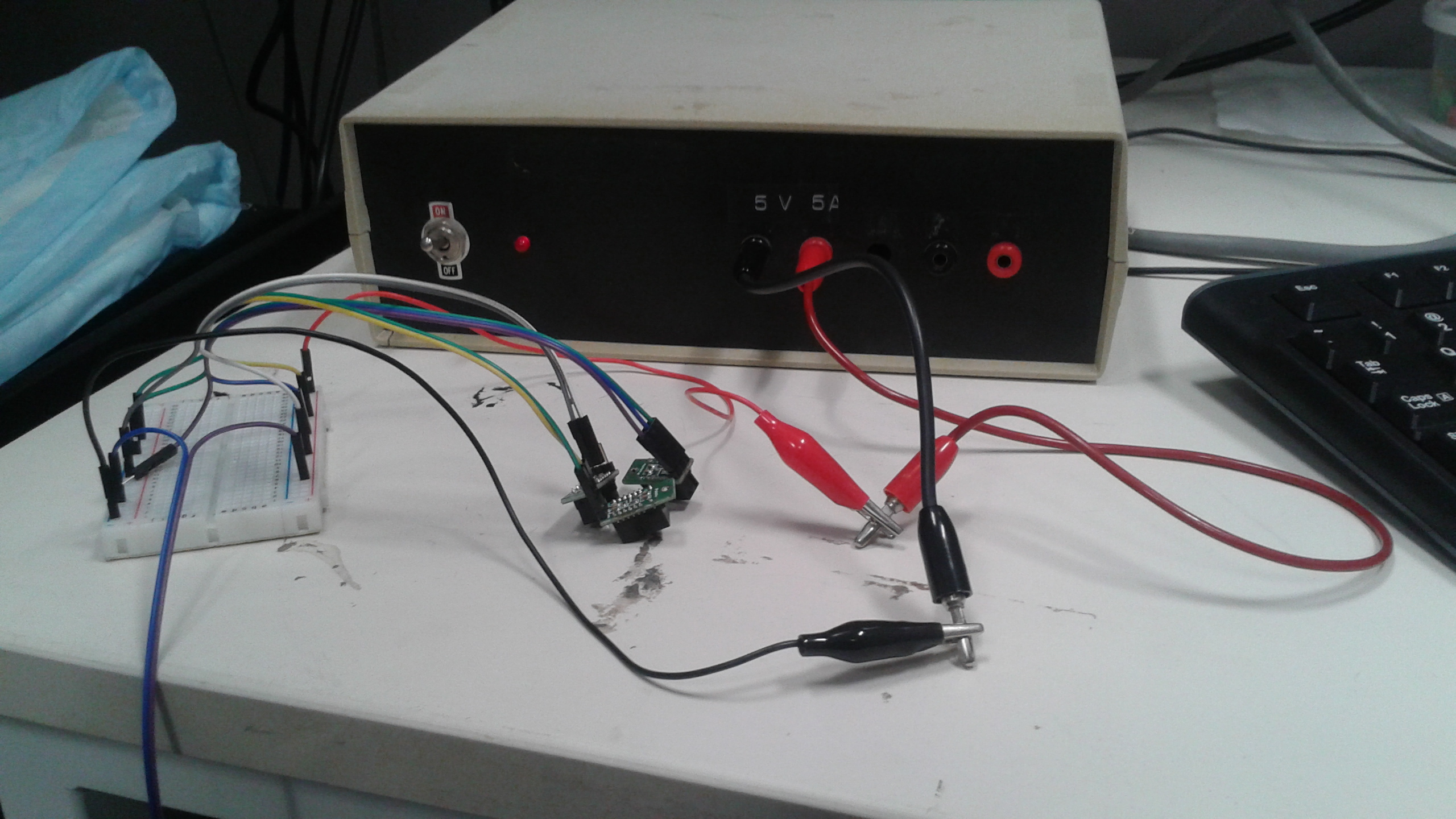
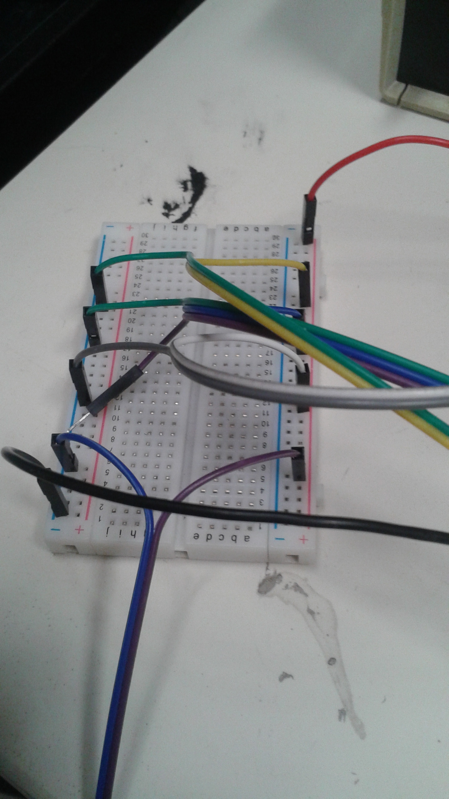
OK, so I went back and did some testing. I removed all the sensors and tried only one at a time. One sensor works fine. Two work fine, but three or more start to flicker as described before. Here are some pictures:
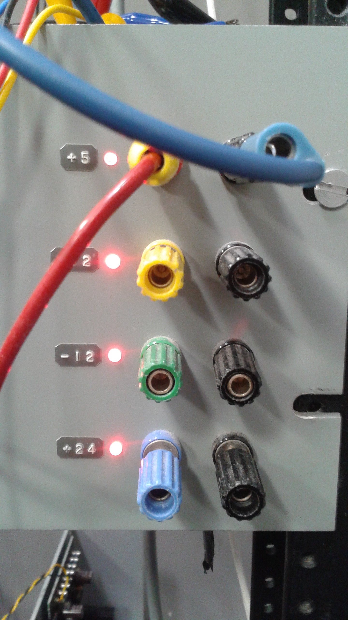
From there it is connected to a front panel. Here is the back of said front panel. The red/yellow are connected to the positive terminal while the blue/black alligator clips are attached to ground. They are attached to a piece of wire that I soldered on:
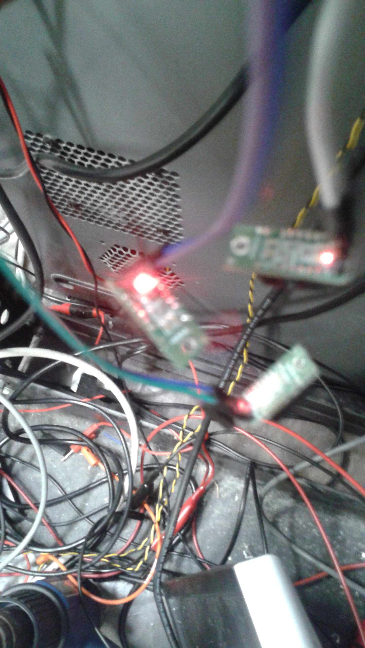
Those alligator clips go into the Vin and Gnd respectively of three sensors shown here, and all three of them are on (flickering). It’s a bit hard to see but I’m 100% sure the positives are going to Vin and Gnd is going to Gnd:
When I disconnect one of the sensors then the other two work fine. The light goes off and when I pass my hand in front of them it turns on. When I measured the voltage accross the terminals of each sensor it read 5.00V on the nose. What’s going on?
Thank you for the pictures and extra information . Since the problem occurs once you add a third sensor, it sound like a power issue. Note that these sensors draw current in quick bursts, so a digital multimeter will probably have a hard time detecting any kind of drop in voltage. You might get better results by adding a capacitor (>10uF) across the VIN and GND pins of each sensor (as close as you can to the board) to help compensate.
I added 47 uF caps to all the boards and that seems to have done the trick. A suggestion for your breakout board is to add a space to put an SMD cap on btw Vin and GND? If people don’t want it they could cut it off like the screw hole part on the other side. thanks anyways!
Hi, I know this is an old post but maybe you’re still monitoring…
I have nearly the same setup as described here - I recently bought 40 of the Pololu sharp sensor boards (GP2Y0D815Z0F .5-15cm) and built 4 sensor boards for a game with 8 sensors on each board. Power is connected in parallel from a decent sized regulated 5v power supply and outputs are going to an Arduino.
One or two sensors (no matter which one or two) work perfectly as expected. As soon as I connect more than that, they all start flickering randomly. I thought maybe it was stray IR somehow bleeding from one sensor to the next but I have no reflective surfaces nearby and I covered individual sensors to block any potential Ir emission to other sensors with no effect.
I read about adding a capacitor in the description of the sensor but wasn’t sure what was meant by “improving performance.”
From what it sounds like, it seems the capacitors may be the answer to my problem. Can someone tell me if this should be a polarized cap or non-polorized (does it matter?)
Secondly, could someone explain why the capacitor is needed? I mean, I know what the capacitor is for but my power supply is fairly large (6 watts) so I can’t see how a few mW worth of sensors would be browning out.
Your situation does sound like another case where adding a capacitor to each of your sensors would help. It does not matter if they are polarized or non-polorized.
The extra capacitors are helpful with these boards because the sensors draw a significant amount in bursts, so if many of your sensors draw a burst at the same time it might be tough for the supply to accommodate them all fast enough.
If adding extra capacitors does not help, can you post some pictures of your setup?