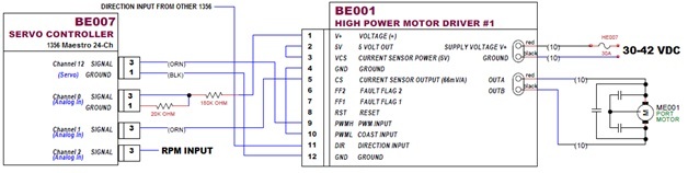
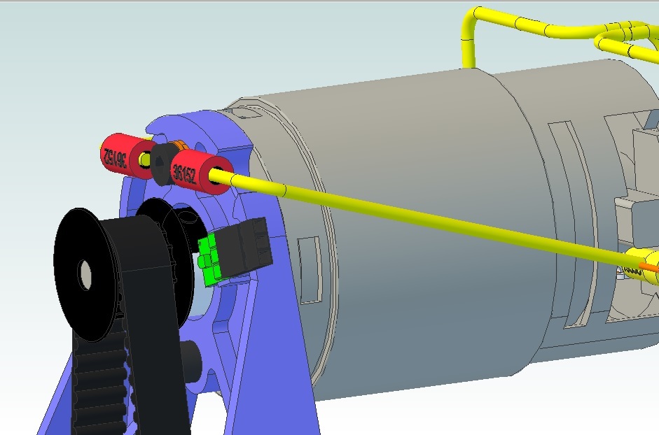
I’m designing a remote control boat that is using a P/N 1356 Mini Maestro 24-channel USB Servo Controller outputting a PWM signal (Channel 12) to a P/N 1457 High-Power Motor Driver 36v20. I’m feeding back the motor supply voltage (via 9:1 voltage divider circuit (180K Ohm/20K Ohm) and motor current to the P/N 1356 Mini Maestro 24-channel USB Servo Controller (Channel 0 and Channel 1). Motor Primary power is volt Li-Ion battery assembly (minimum (cutoff) voltage is 30V and max battery voltage is 42V, Nominal is 39.7V), thus the voltage divider circuit for motor voltage (Channel 0 max analog input voltage 5V).
Motor Max RPM = 18,720 @ 36V (520 RPM / Volt)
Prop Max RPM = 7,500
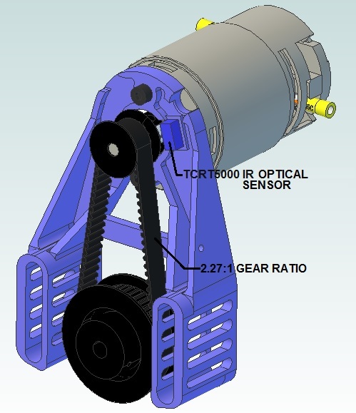
Drive Gear Ratio = 2.27:1
Desired Motor RPM = 17,025 or 32.75 Volts (Approx 21A = 688W (.90HP))
Since my max RPM is determined by the propeller, I need to monitor the RPM and adjust the throttle so that I do not exceed this design limit. Feedback to the shore based unit will display RPM to the operator.
My question is about measuring the motor RPM. I would prefer a self illuminated optical sensor over a Hall Effect sensor (I don’t want to glue magnets on the shafts or pulleys). The motors/prop shafts are mounted in the interior, closed sections of the boat, so sunlight should not be an issue. I would prefer an off-the-shelf sensor with frequency to voltage converter set-up.
If there is another method using the 1356 Mini Maestro I would appreciate that.
Another question: How do you heat sink the P/N 1457 High-Power Motor Driver? The web page description did not cover how to heat sink the board.
We do not carry an optical encoder with an analog voltage output and there are no provisions for using interrupts with the Maestro so it would be difficult to read the square wave output from an encoder at the sort of frequencies you are considering using. In general, I am having difficulty seeing why you have picked the Maestro to be the controller for your system since you are not using any servos or even an ESC that uses a standard RC servo signaling method. Is there a specific reason you chose it? To me, a more general microcontroller board like one of our Arduino compatible A-Star 32U4 boards seems like it would be easier to use for a system like this.
As for heat sinking, we do not have any specific advice for it, and we generally view adding a heat sink as an advanced modification that should only be made by those who have experience with that kind of thing.
Nathan,
Thanks for the reply.
My schematic only shows the motor and interfaces with the High Power Motor Controller. I’m actually going to control 22 or more servos with individual actions (none in parallel) using three 24-Channel Maestros…
Initially my design used a PWM controllers and DPDT reversing relays – kind of clunky, complex, expensive, heavy and bulky. Your 1457 HP Motor Controller fits my bill very nicely.
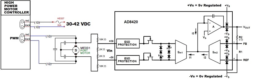
Maybe another approach may work to determine RPM. Since I know the RPM vs. voltage for this motor, is there a way I can measure OUTA / OUTB voltage and be able to invert the signal when in Reverse, i.e. will an analog input to the Maestro handle a +/-5 volt input signal?
RPM = MV * 520
Where;
MV = Voltage measured at motor brushes
RPM = Motor’s RPM
However, the maestro analog input max is 5 volts, so MV into Channel X is 1/10 (via voltage divider – 180K/20K).
Resulting equation would be: RPM = V2 * 5200
Where;
V2 = Voltage input to Channel X
RPM = Motor’s RPM
The side of OUTA and OUTB that are positive and negative changes depending on the direction that the motor is being driven. Also, there are conditions where those pins are connected to only the motor terminals, and since the motor will function as a generator if it is spinning and left disconnected, it is possible for higher transient voltages to be present on those pins. Also, although the motor speed will be roughly equal to the voltage applied under a free spin condition, the actual speed for a given voltage will be lower under load . However, if your purpose is to simply limit the maximum RPM, you might be able to use the approach you mentioned to limit the maximum PWM duty cycle to the motor controller:
Thanks Nathan,
Since the rotating portion of the motor/prop/belt drive system has relatively little mass, I don’t anticipate that back “generated” voltage will be an issue.
I’ve done a little more research on inverting the motor voltage on the sense line and come up with an AD8420 Instrumentation Amplifier. Gain on the amplifier is 1.0, so Vout should follow Vin but stay postive. Vin will be 1/10 motor voltage. I’m communicating with Analog Devices just to make sure that is how it will work.
Also concerned about the PWM voltage to the motor. The motor is slow enough reacting to the PWM voltage, but the Op-amps in the Instrumentation amplifier will react to the pulses. Don’t know if the caps on the motor will smooth out the PWM voltage any.
If all this is true, I’ll have to make up a small PCB with three AD8420’s on board.
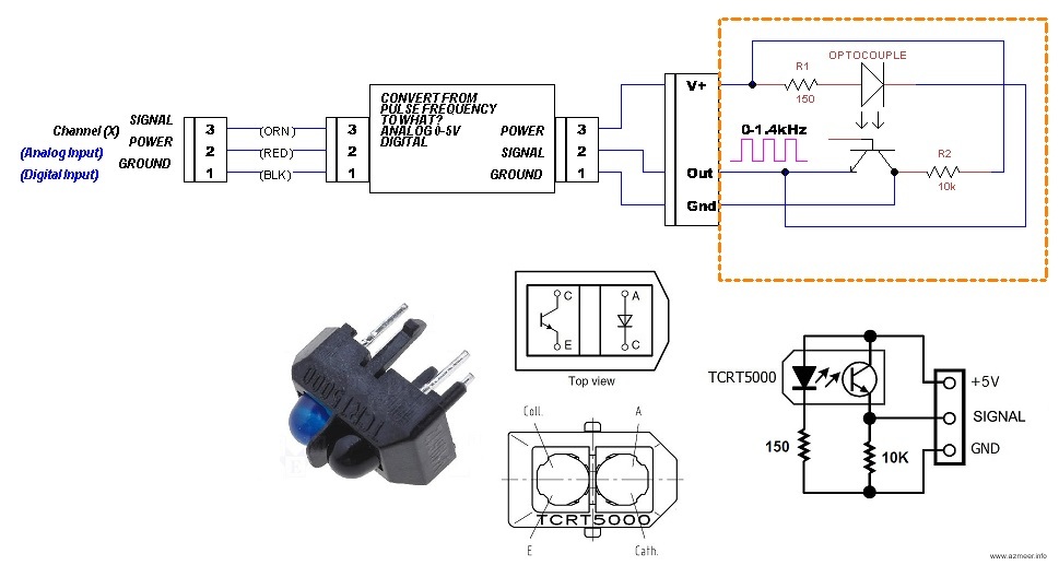
OK, lets take another track. I’ve been looking for an optical sensor to use as an RPM sensor and found a part, TCRT5000, that has both an Infa-Red LED source and a Infa-Red Receiver.
Now my questions is: "What kind of signal can the Maestro process? Will I have to use and analog (0-5) input? or a digital input? Can the Maestro Digital channel be used as a counter and the count be processed as RPM?
I’ve marked the motor pulley with four “target” colored stripes, so the IR detector will output 4x the RPM. Max RPM possible is approx 22,000 RPM. With 4 pulses per revolution, the frequency would be 1.4kHz.
The Maestro can read analog inputs on channels 0-11 and digital inputs on channels 12-23 (which we mention in the “Channel Settings” section of the Maestro User’s guide). (Since the Maestro can read either of those signals, its up to you which is more appropriate for your system.) However, as I said before, there are no provisions for using interrupts with the Maestro so it would be difficult to read the square wave (digital) output from an encoder at the sort of frequencies you are considering using.
I am not aware of any off the shelf components that will convert a pulse frequency to an analog voltage (as you show in your diagram), though they might exist somewhere.
That IR sensor you mentioned looks like it would function in a manner very similar to our QTR-L-1A reflectance sensor, and we also use the same basic circuit for our Optical Encoder Pair Kit for Micro Metal Gearmotors as well. If you want to build your own optical speed sensor, the oscilloscope captures on the optical encoder page might be useful for you to look at when designing the targets to get a useful signal.
Nathan,
Thanks for your help with the IR detector (QTR-L-1A - Reflectance Sensor). I’ve found a TI product (LM2917) that converts frequency to voltage. The QTR-L-1A is much smaller than the TCRT5000 IR Sensor I found earlier. I’ve redesigned my motor mount (a printed part) to accommodate the QTR-L-1A (with 90 header) and drive pulley with 180 black/white paint. I’ve designed a circuit board to accomplish this. Just need to have the $$ to order parts and breadboard this circuit to test it out.
Changing subjects now…I need some direction on what to use to control the entire ship-side system (microprocessor?), what duplex wireless communication (1,000 to 1,500 yard communication range) and the land based control and monitor system including human interfaces.
We make a number of different programable controllers that might be helpful for something like that. Our A-Star boards have a number of available general purpose IO pins and are Arduino compatible, so they will work with the Arduino library to control the Maestros over TTL serial.
I do not know of any wireless communication systems I would be able to recommend for communicating at the sort of distance you mentioned.
This design is needlessly complex and costs to much.
Once you answer your question about over all control and find a microprocessor you will see that you don’t need the controller board you are using as the uP can preform it’s function. You will also see you don’t need to convert frequency to voltage because the uP can time the pulses. The title uP costs less.
Your communications requirements are hard to do because you want full duplex over a long distance. One-way is easier as it does not require a powerful transmitter on the vehicle. You did not say what data rate you need? What are you doing with this data link? You can save something by playing with antenna gain. The land based antenna, I assume can be large but is there a maximum size antenna you can put on your boat? Do you really need several kilometers of range?
I think that I was a little too ambitious on the first attempt. So, a totally new direction:
To get my boat up and running quickly, I’m now looking at one way communication. I will still have three (3) 1457 high power motor drivers. I would use a standard RC radio with one throttle and rudder.
My question is; “Could one 24Ch mini Maestro PWM output (Ch12) be split out to drive three motor drivers? i.e. one throttle RC input to the Maestro, with one PWM output paralleled to the three motor drivers?”
I know that I would not have differential motor control, but I would be able to get the boat in the water and start having some fun.
I’m using the 24ch Maestro for future expansion. I know that right now the 24Ch Maestro is a little overkill for this configuration. Unless you have a device that will take Servo Input and output PWM.
It is not practical to read hobby RC pulses with the Maestro. Our Simple Motor Controllers can drive a motor using PWM from RC pulses, however we do not have one that works at the same voltage and current as the High-Power Motor Driver 36v20 CS. With some coding, a small inexpensive microcontroller board like our A-Star 32U4 Micro should be capable of doing something like reading RC pulses and generating PWM to control motor drivers. The PulseIn Adruino Library can help you get started with that.