I had a problem with this component VNH5050A and I need your support.ᅠ
My test bench is composed by:
- A PCB board (created by myself), where I solder the VNH5050 with the same resistors and capacitor shown in the typical application found on datasheet.ᅠ
- Input capacitor of 1000 uF on supply voltage.ᅠ
- A DC Brushed Motor.
- Signal generator.
- Oscilloscope.
- DC Power Supply (Work condition 10V without current limitation; Max 50V, 30A).ᅠ
I had this problem with two different DC Brushed Motors (motor A: max operate at 16V, 5 A; motor B: works max 16V, 20A) without load.
The configuration of VNH5050 is: PWM [0-5]V, INA connect to 5 V, INB connect to GND, ENA_DIAGA and ENB_DIAGB pull-up with 3.3 kOhm to 5V.ᅠ
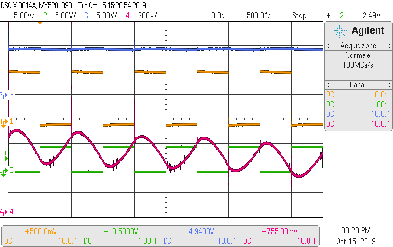
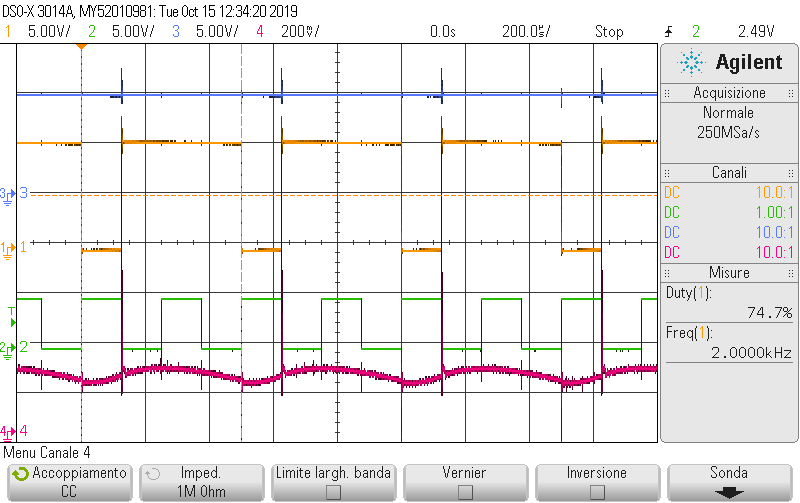
I read from datasheet that I could work up to 20 kHz PWM Frequency but when I reach 5 kHz of PWM Frequency I see on oscilloscope the output does not follow the input PWM signal. The output jumps some PWMs input, for more details I attach the images of the oscilloscope for the two motor.ᅠ
Legend of oscilloscope’s signals: Channel 1 (yellow) VoutB (voltage between outB and GND), Channel 2 (green) PWM input, Channel 3 (blue) VoutA (voltage between outA and GND), Channel 4 (pink) Current sense pin after filter (copy from datasheet).ᅠ
I also try the configuration with 1kHz of PWM and I see the correct behaviour of the component. I attach the image for clarity, the signals of oscilloscope are the same of previous attempt.


