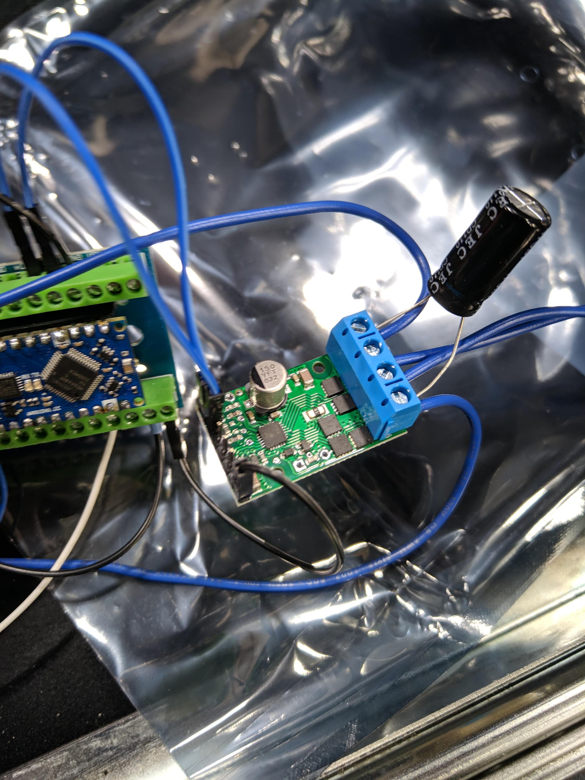
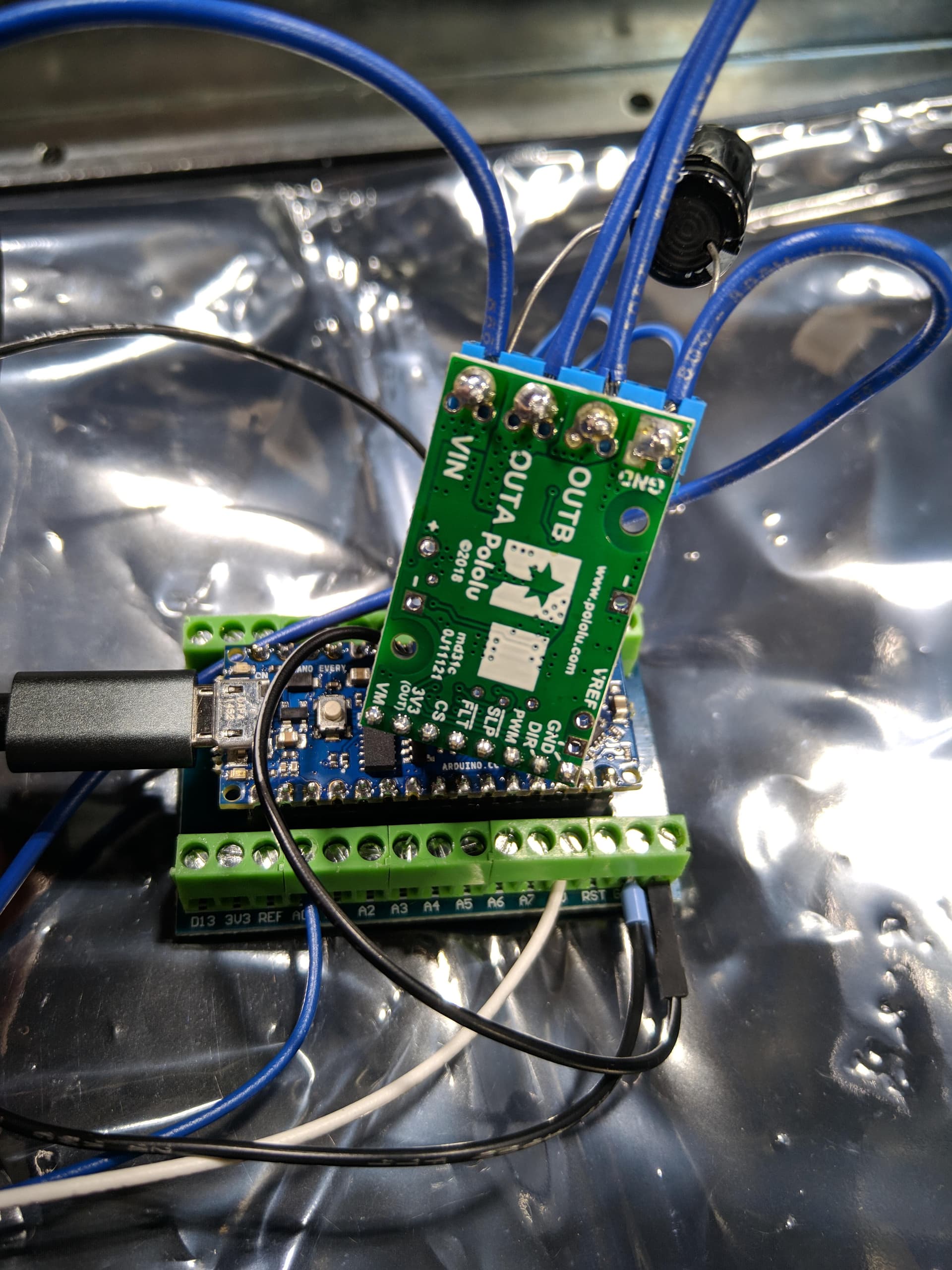
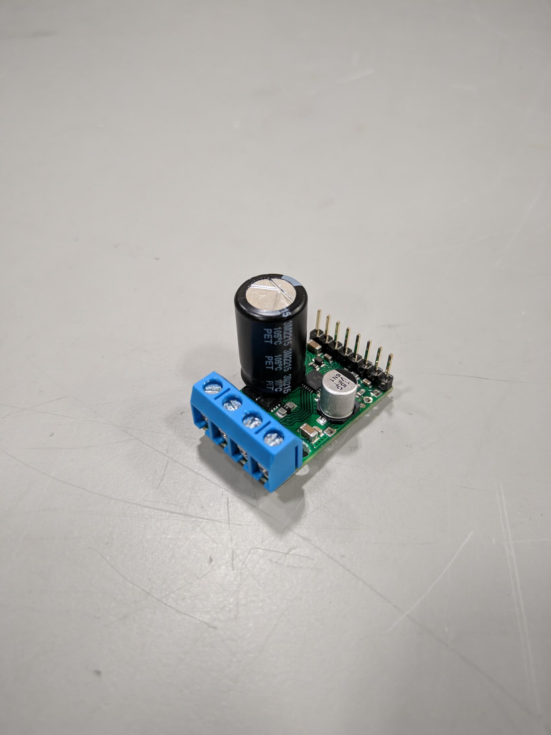
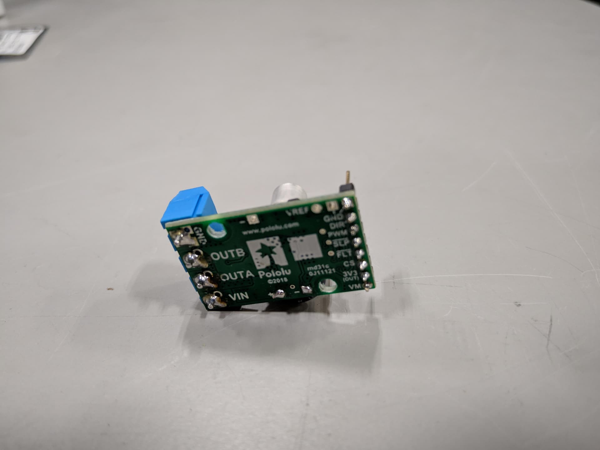
The motor is connected to OUTA and OUTB on the driver board. There is a 25v 1000uf or 16v 470uf capacitor between VIN and GND (I’ve connected two different drivers to the system with no effect, each with a different capacitor). The positive terminal on the power supply is connected to VIN. The negative terminal on the power supply is connected to GND.
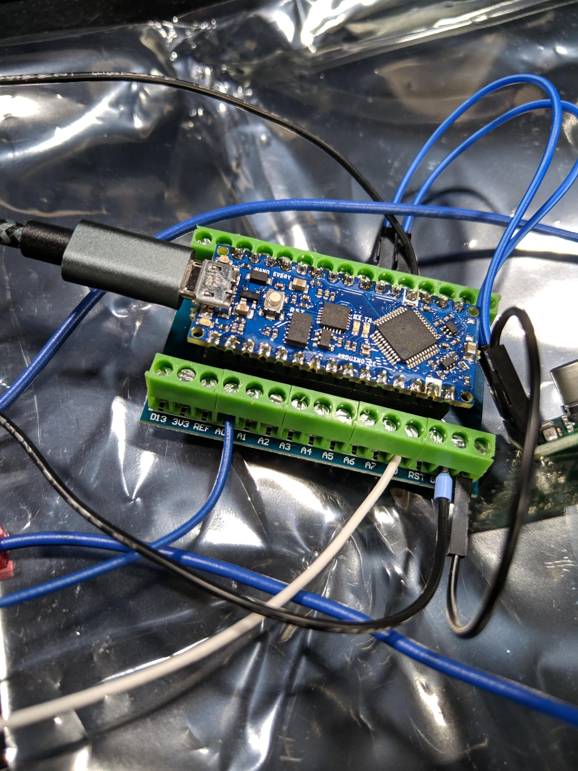
D2 and D3 on the Arduino are connected to DIR and PWM on the driver board. VIN and GND on the Arduino are connected to VM and GND on the driver board.
The Arduino code is as follows:
const int motorDirection = 2;
const int motorPWM = 3;
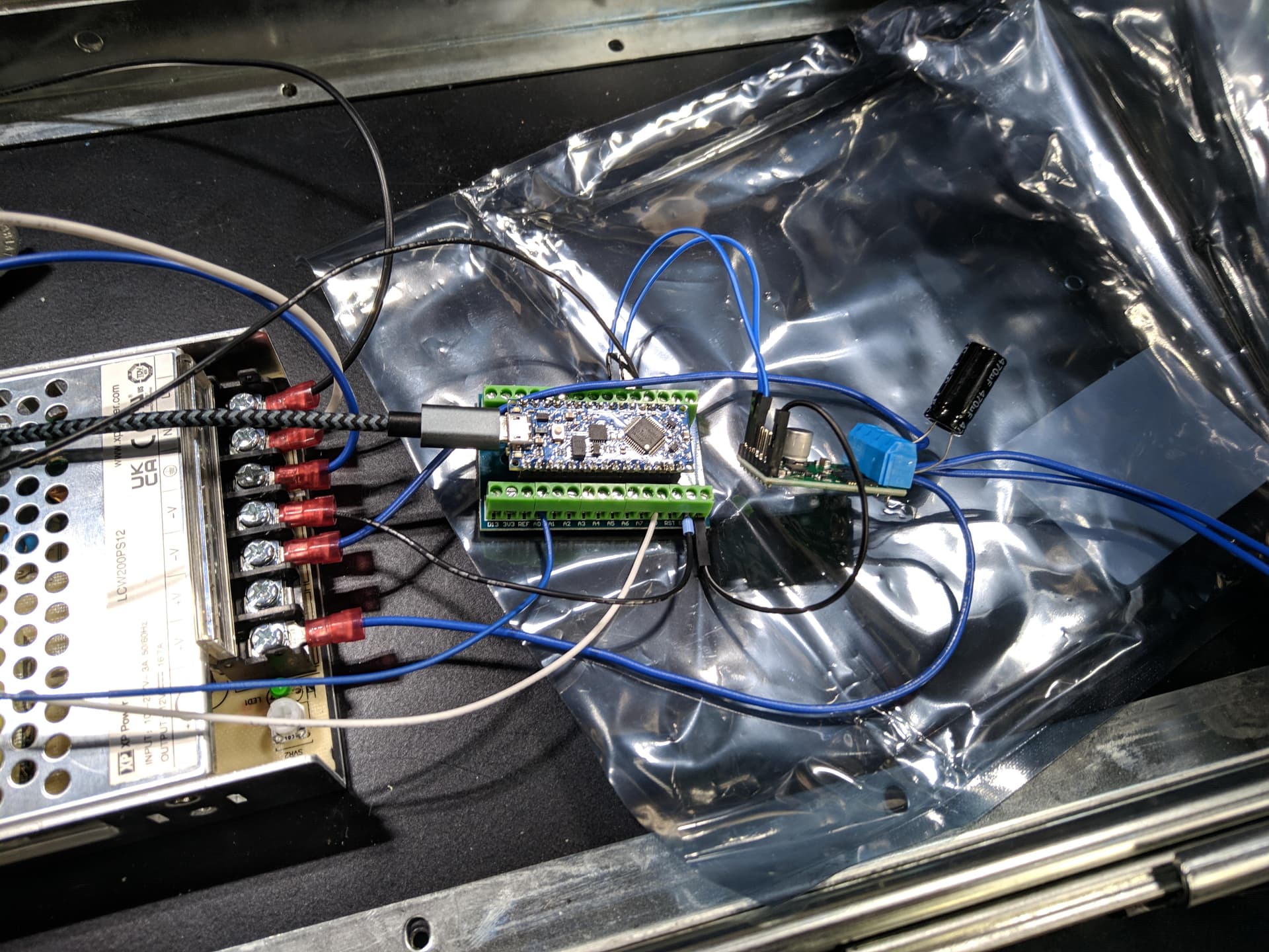
When I plug it in, the Arduino boots fine, but the motor starts turning very slowly. I tried changing the duty cycle in the Arduino code, but that had no effect. I measured the two DC terminals on the power supply, and it is providing 12v, but the motor is drawing 0.61A. I was able to get this system working at one time, but I’m doing something wrong now and I can’t figure out what it is. I tried removing the Arduino screw terminal board from the system, and that also had no effect. All the soldering looks good to me. I’ve also replaced both the driver and the motor to no effect. But if I connect the motor directly to the power supply, it functions as expected. The driver also gets extremely hot. It hasn’t burned itself out yet, but I’m not sure if that’s normal for this board.
The G2 High-Power Motor Driver 18v17 is probably not appropriate for a motor as powerful as the motor you linked to, which has a stall current over 100A. It is possible that the motor’s startup current is triggering the driver’s current limiting right away leading to the strange behavior you are seeing. In general we recommend using a motor driver that is rated to handle the stall current of your motor continuously, so something like one of our high power RoboClaws or MCP Advanced Motor Controllers would probably be more appropriate here. Or, if you are really constrained on space, our G2 High-Power Motor Driver 18v25 is a bit more powerful than the 18v17 and has a better chance of working in your application (and would be a drop-in replacement if it does work).
You might be able to get this driver working by implementing some kind of acceleration limiting, but I think a better approach to start out here would be to test your drivers with a lower power motor until we confirm they have not been damaged by trying to use them with the motor you linked to. Do you have a lower power motor available to test with? Can you post some pictures of your actual setup that show how everything is connected, including ones that show the soldering on your boards?
Yeah, perhaps I should’ve chosen a different driver, but I was able to get this driver to work as intended at one time. But my current driver should still function because the current my power supply is capable of producing is 16.7A, which is below the rated current of the driver. I also do not have a different motor to test.
Motors will briefly try to draw their stall current when starting abruptly, and even if your power supply limits the current, using this driver with a motor that is too powerful could still be risky. The driver’s current limiting should help protect it, but this might come at the cost of degraded performance if the current is never allowed to rise to an amount necessary to get the motor fully going.
Separately, when a powerful motor is decelerated, the back EMF can often generate a large reverse current that then produces a large voltage spike if the supply cannot absorb it. You mentioned that the driver worked as expected at one point; did you notice if it stopped working during or after any particular event, such as stopping the motor? It is usually a good idea to use an oscilloscope to check whether damaging voltage spikes could be an issue. If so, you add something like a TVS diode or shunt regulator to help deal with them.
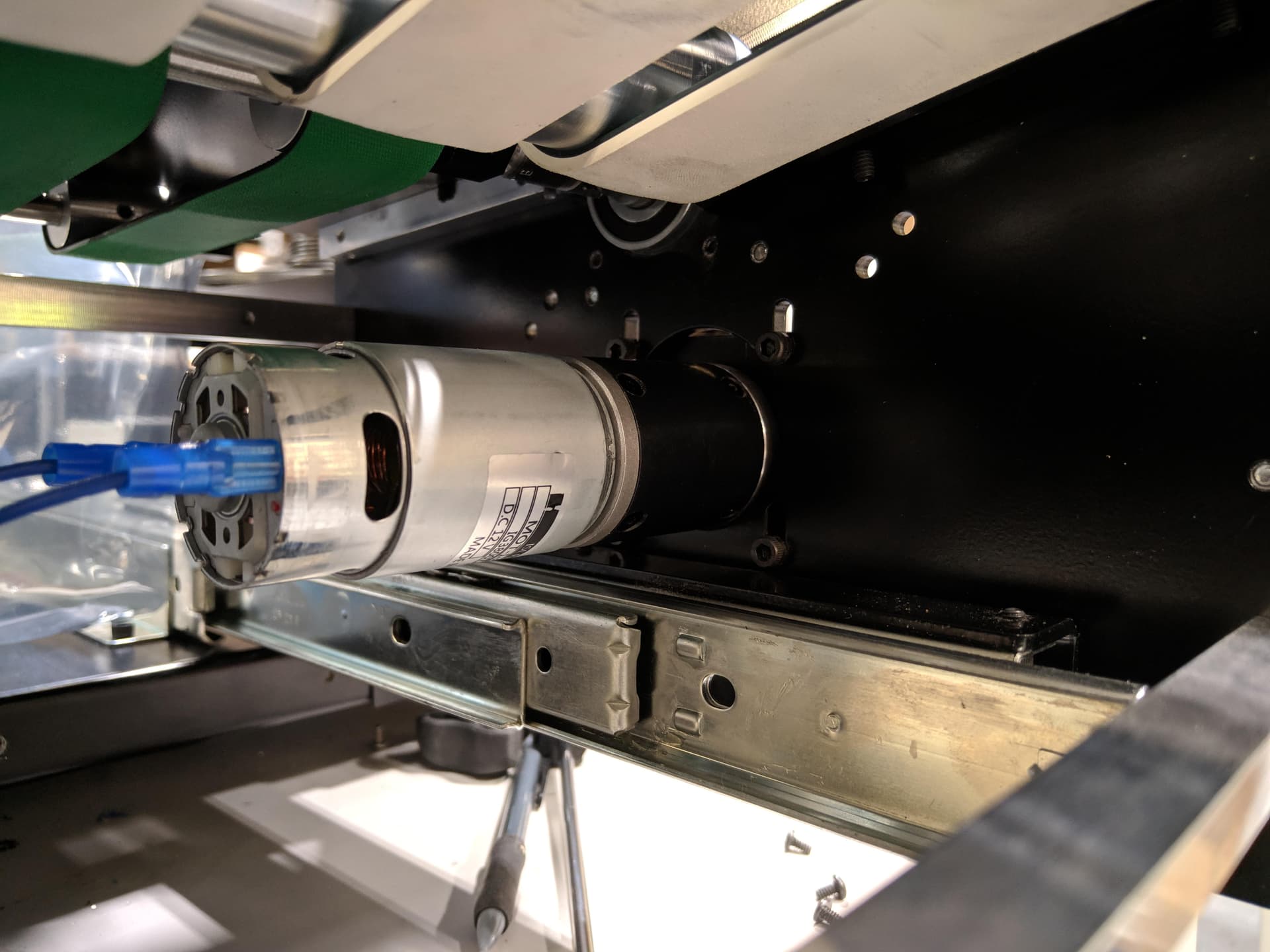
Your soldered connections look okay, but the wiring is difficult to follow. I would especially encourage replacing the black jumper to your Arduino’s VIN pin with some other color, ideally red. Additionally, glare from the photo is obfuscating the labels on the power supply, and all of the other wires being the same color is not helpful either.
It looks like you do not have a GND connection between your driver and microcontroller. Missing that connection could definitely lead to issues, and could potentially damage them, so please add that. If you add that and test the driver without the motor connected, do you see the expected behavior if you monitor the voltage on the driver’s output pins? Does the driver still heat up a lot if it is run without a motor connected?