I have a rather old LV-168 and I’m trying to get it to respond to analog input of 0-5 V by running the motors backwards for 0<V<2.5 and forward for 2.5<V<5.
I don’t have an actual motor attached, and I’m monitoring the output using a scope.
The problem is that I don’t seem to get negative voltages (to correspond with the backwards motion) out of the motor outputs. Only positive PWM at around 8V.
How are you using your oscilloscope to measure the output voltages? Can you describe or post a picture of how you have the scope connected to the Orangutan?
In addition, it is a little worrying that you see 8 V on the outputs sometimes, since the maximum input voltage on the Orangutan LV is 5 V (and the outputs will never go higher than the input). What are you using to power the Orangutan?
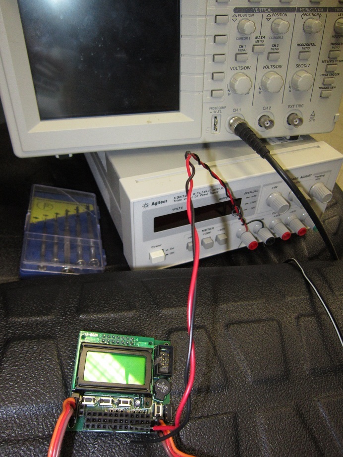
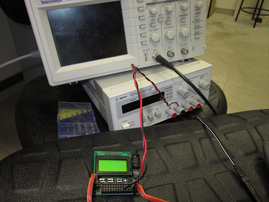
Here’s some pictures. I’m attaching the scope to the motor sockets. You can disregard the other wiring- they’re used for the analogue input and aren’t attached properly in these pictures.
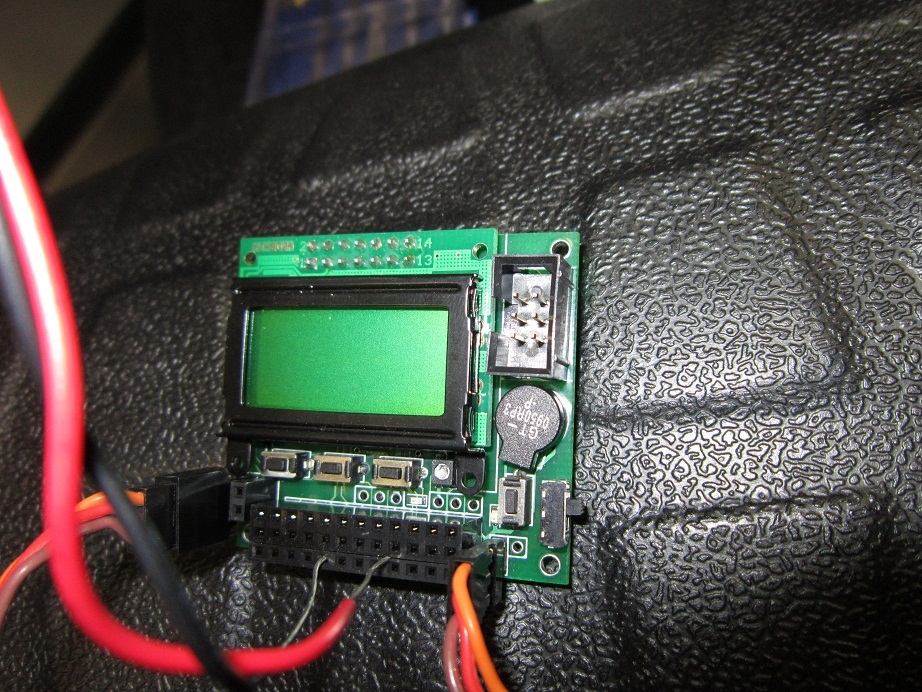
It looks like you have an Orangutan mega168, not an Orangutan LV-168. You are correct that the Orangutan mega168 can take an input voltage of up to 10 V. (I have corrected the title of your original post.)
Your pictures still do not show how you actually have the oscilloscope probe connected to the wires coming from the Orangutan. Do you have the probe’s ground connected to one of the motor output pins? That is not a good thing to do because it shorts the output to the oscilloscope’s ground. In your case, it might not have caused a problem if you are using a battery as a voltage source and have no other ground connections between the Orangutan and the scope, but in general, connecting a probe ground to a point on a board that is not ground is likely to create a short that damages either the board or your oscilloscope.
What you should do instead is use two probes, one for each side of the motor output, with both of the probes’ grounds connected to a ground on the Orangutan. Then, you can manually compare the voltage on the two scope channels, or you can use your scope’s math functions to display a waveform of the difference between the two channels. Please try measuring the motor outputs this way and see if you get the right voltage levels for the outputs driving in both directions.