I’m trying to get some basic readings from the MMA7361L Accelerometer (with Voltage Regulator) and struggling. I’m running a Baby Orangutan so I cannot get feedback to an LCD. I’m using the example at: pololu.com/docs/0J20/3.a
My connections are very simple:
7.2v Connection -> VIN
Ground -> Ground
ACD7 (Baby Orangutan) -> X
(have also tried ACD6 and replacing ‘TRIMPOT’ with 6)
Basically, the red led is on at about 75% brightness and never changes irregardless how fast I move the unit around.
Readings:
3v3 pin: 3.2v
X pin: 1.5v
Y pin: 1.5v
Z pin: 2.0v
None of these values seem to change as I move the unit around.
Is it possible I have a bad unit or am I doing something basic very wrong?
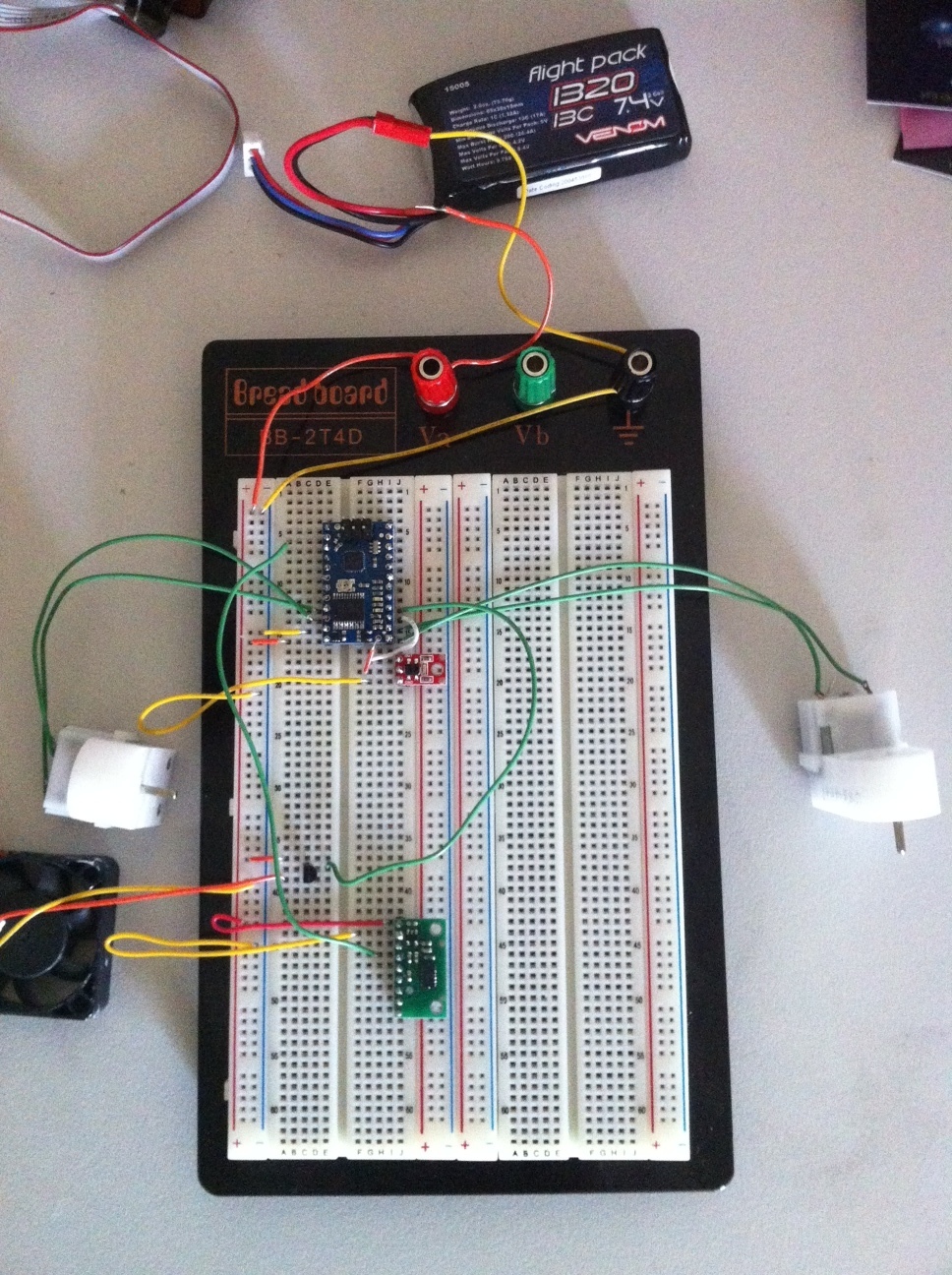
Is the ground connected between the accelerometer and the Baby Orangutan? Which example are you using? Have you changed the code at all? If you have, can you please post your code here? How did you measure those readings? A picture of your setup might help us notice problems.
You’ll see the Accelerometer is connected directly to the power source and to the main ground. There is only one line going to the Baby Orangutan and that is from X to ADC6.
I’ve been testing using the code as it is in the tutorial (just replacing TRIMPOT with 6):
#include <pololu/orangutan.h>

/*
 * analog1: for the Orangutan LV/SV-xx8 or Baby Orangutan B
 *
 * This example uses the OrangutanAnalog functions to read the voltage
 * output of the trimpot in the background while the rest of the main
 * loop executes.  The LED is flashed so that its brightness appears
 * proportional to the trimpot position.  This example will work on
 * both the Orangutan LV/SV-xx8 and Baby Orangutan B.
 *
 * https://www.pololu.com/docs/0J20
 * https://www.pololu.com
 * https://forum.pololu.com
 */

unsigned int sum;
unsigned int avg;
unsigned char samples;

int main()
{
  set_analog_mode(MODE_8_BIT);    // 8-bit analog-to-digital conversions
  sum = 0;
  samples = 0;
  avg = 0;
  start_analog_conversion(6);  // start initial conversion

  while(1)
  {
    if (!analog_is_converting())     // if conversion is done...
    {
      sum += analog_conversion_result();  // get result
      start_analog_conversion(6);   // start next conversion
      if (++samples == 20)           // if 20 samples have been taken...
      {
        avg = sum / 20;             // compute 20-sample average of ADC result
        samples = 0;
        sum = 0;
      }
    }

    // when avg == 0, the red LED is almost totally off.
    // when avg == 255, the red LED is almost totally on.
    // brightness should scale approximately linearly in between.
    red_led(0);                 // red LED off
    delay_us(256 - avg);
    red_led(1);                 // red LED on
    delay_us(avg+1);
  }
}
I connected a multimeter and kept it connected while pushing the setup around, the voltage didn’t waver at all on any of the x y z channels. My understanding is that it should move between 0 and 3.3 Volts depending on the movement of direction, and settle back at 1.65V when no movement is occurring.
You’ll need to ignore all my other bits and pieces which work quite well. Two motors can be driven using PWM, the Fan can be turned on/off from the Baby Orangutan using the transistor, the Reflectance Sensor works. So from what I can tell there may be an issue with the Accelerometer itself?
What color is the “X” mark on the bottom of your accelerometer PCB? Instead of moving the board around, can you just rotate it to align different axes with gravity and measure the outputs with your multimeter? For example, what do you measure if you turn it upside down?
Separately, it’s difficult to be sure, but it looks like some of your solder joints on the Baby Orangutan (including ADC6) might be pretty bad.
Okay as you said when I tip it I can get the voltage for X and Y to change. Don’t seem to have the same results with Z for some reason. I’m pretty sure the ADC6 is connected okay as when I remove the cable to it the LED is very dim (as it should be when 0V is being sent to it).
Am I completely missing the point of the accelerometer? What should I be doing to simple detect if my robot vehicle is moving within a certain axis (e.g. forward/reverse)? Because unless it’s tipping I’m not sure the values are going to be helpful to me. Sorry for my ignorance on this.
The point of the tipping test was to verify that the accelerometer is working properly and detecting accelerations. If it is, the problem is with your code or connections. If it isn’t, let’s just look at the accelerometer for now.
Ultimately, I think you should be using a better program to communicate the output of the accelerometer. For example, you could turn the LED on if the x axis voltage is above a certain threshold, or you can use the program you have now but rescale it so that 1.5V corresponds with the LED fully off and 2V corresponds with the LED fully on. If you are using our USB AVR programmer, the easiest way to debug your setup would probably be to use it as a USB-to-serial adapter, which would let you display the accelerometer voltages via a terminal program on your computer.
Also, keep in mind that the accelerometer measures acceleration, which is not always the same thing as “motion”. If you are moving your robot around at a constant velocity, the acceleration is zero. If you are trying to track the velocity of your robot, you will need to integrate the acceleration.