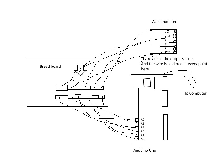
I have been trying to use this accelerometer with an arduino board but there has been a lot of trouble. I have been using the code that was given by arduino to read accelerometers. I soldered the wires and i have triple checked that each one is going to the correct place. I keep getting 400 for all the values most of the time. the three output values should be 0,0, 440. because there should be no force on two angles and the force of gravity on the last one.
Here is the code.
/*
 ADXL3xx

 Reads an Analog Devices ADXL3xx accelerometer and communicates the
 acceleration to the computer.  The pins used are designed to be easily
 compatible with the breakout boards from Sparkfun, available from:
 http://www.sparkfun.com/commerce/categories.php?c=80

 http://www.arduino.cc/en/Tutorial/ADXL3xx

 The circuit:
 analog 0: accelerometer self test
 analog 1: z-axis
 analog 2: y-axis
 analog 3: x-axis
 analog 4: ground
 analog 5: vcc

 created 2 Jul 2008
 by David A. Mellis
 modified 30 Aug 2011
 by Tom Igoe

 This example code is in the public domain.

*/

// these constants describe the pins. They won't change:
const int groundpin = 18;             // analog input pin 4 -- ground
const int powerpin = 19;              // analog input pin 5 -- voltage
const int xpin = A3;                  // x-axis of the accelerometer
const int ypin = A2;                  // y-axis
const int zpin = A1;                  // z-axis (only on 3-axis models)

void setup()
{
  // initialize the serial communications:
  Serial.begin(9600);

  // Provide ground and power by using the analog inputs as normal
  // digital pins.  This makes it possible to directly connect the
  // breakout board to the Arduino.  If you use the normal 5V and
  // GND pins on the Arduino, you can remove these lines.
  pinMode(groundpin, OUTPUT);
  pinMode(powerpin, OUTPUT);
  digitalWrite(groundpin, LOW);
  digitalWrite(powerpin, HIGH);
}

void loop()
{
  // print the sensor values:
  Serial.print(analogRead(xpin));
  // print a tab between values:
  Serial.print("\t");
  Serial.print(analogRead(ypin));
  // print a tab between values:
  Serial.print("\t");
  Serial.print(analogRead(zpin));
  Serial.println();
  // delay before next reading:
  delay(100);
}
I am sorry you are having trouble reading your sensor. We have two boards that use the MMA7341LC chip: one that has a regulator and one that does not have a regulator. Which of those two are you using? Which Arduino board are you using? Can you also post pictures that clearly show your connections?
Your raw data looks mostly okay to me. Please note that the accelerometer readings are going to be centered around half the voltage of the 3V3 pin (which should be about 3.3V), or 1.65 V, making the center value about 337 (where 0 is 0V and 1024 is 5V). When converted properly to units of g, most of your readings are close to 1 g in magnitude.
By the way, I appreciate your attempt at making your diagram depict reality, but in the future it would be much more helpful if you just showed what was connected to what in a clear way. You can see an example of a cleanly labeled schematic diagram here:
You can control the g-select (sensitivity selection) pin with any of your Arduino’s 5V digital outputs. The pin is internally pulled low, so you should only need to write code if you want to change it from its default setting. Something like this should work:
 int gSelectPin = 3;
digitalWrite(gSelectPin, HIGH);
When i do that the numbers do change but the conversion doesn’t work.
here is the data for the chip being flat on the table which should read 0,0,-1
348 354 326
349 354 326
here is the data for the chip being upside down on the table which should read 0,0,1
346 350 373
344 351 376
for some reason the center is around 354 and 20 units = 1g
I cant figure out why this is?
Like we mention on the product page for that accelerometer, the value of the center of the analog voltages is dependent upon the voltage of the 3V3 pin. So, it might be that the voltage is not quite at 3.3V when you are getting your raw data. There are various reasons this might be, but a good way to get around that is to use an analog input and measure the voltage on the 3V3 pin, and then use that value as the center for your calculations.
Hi, I am using the accelerometer MMA7341L ±3/±11g, I would like to know where the 3V3 pins are connected since it has two and one is next to “g-select”, I will use it with a PIC16f76A. greetings and thanks Pololu team!
The 3V3 pins are both 3.3V outputs supplied by the onboard 3.3V voltage regulator. They are connected to each other, and one is located next to the g-Select pin to provide a convenient way to pull g-Select high with something like a 0.1" - spaced jumper.
Thank you for your prompt response, I understand it, now then the reading at the exit of any coordinate will be the reference to ground or just read through the pic the output of that coordinate? I planned to monitor the voltage at the output of a coordinate with an oscilloscope to have the reference values before starting to program. Thanks J.
I am not entirely sure I understand what it is you are asking. In general, electronics like these should share a common ground, and by convention, voltages in a circuit are measured with respect to ground. For example, if you are using a multimeter to measure the voltage, you would connect the positive probe to either X OUT, Y OUT, or Z OUT, and the negative probe to GND. If you are using a microcontroller like your PIC, you should ensure that there is a connection between GND on your PIC and GND on the MMA7341L before reading the voltages produced at X OUT, Y OUT, or Z OUT.
Thank you very much Jon for your attention, and I managed to get a reading of the midpoint of the voltage in XOUT which is 2.587V approx. (The exchange range is 2,790V - 2,495 approx.). Now I have several doubts:
This variation is minimal even if it is already at 90 °, I would like to know if this is correct and if this variation can be increased since I understand that it can vary from 0-5V (while the G-select pin is 1).
How can I make these values in Volts that XOUT gives me are read and interpreted by the PIC?
The following pins are not connected:
*TEST and 0G
Should I connect them to some port of the pic? or what are these pins of the MMA7341L for?
This is a 3.3V sensor, not a 5V sensor, so its analog voltage outputs will vary from 0V to 3.3V (with the midpoint, 1.65V, representing 0g). This is regardless of whether the g-Select pin is connected high or low. The g-Select pin is used to set the sensitivity of the accelerometer, and pulling it high like you did sets a range of +/-11g. We broadly go over how to convert the analog voltage output of this sensor using the sensitivity (which would be 118 mV/g for your setup, since you are pulling g-Select high) under the “Using the sensor” section of that board’s product page. If you want the output to cover a wider voltage range, you probably want to use the +/-3 g range instead, which you can select by pulling g-Select low or leaving it disconnected.
That section also describes the Self Test and 0-g Detect pins; you should not need to connect them if you just want to read the acceleration values directly like what you are doing. If there is something in that section that is not especially clear, can you tell me specifically what it is you do not understand?
Note that the values you are reporting generally seem too high (with the +/-11g range, 2.587V would indicate a measured acceleration of nearly 8g), so unless you are actually expecting the sensor to be experiencing that kind of acceleration, I suspect you are either using it incorrectly or interpreting its output incorrectly. Can you tell me more about your setup? How are you supplying power to the MMA7341L, and how are you measuring its output? Can you post pictures that clearly show the connections between your accelerometer, PIC, and oscilloscope?
Hi, I made a small sketch of the connections between the accelerometer and the pic (excluding the other connections of the pic), Vin of the accelerometer is 3.3V, but it still gives me the following values: (left-center-right)
With gsel not connected: 1.748V - 1.630V - 1.503V
With gsel connected: 1.780V - 1.657V - 1.536V
Those values seem fine for when g-Select is connected high, but not when g-Select is disconnected. Can you post pictures that clearly show your board and setup? Specifically how are you measuring the voltage at X OUT (multimeter, oscilloscope, reading with your PIC and printing the values, etc.)? It might also help if you post a video that shows your setup.