I have been touting your accel breakout to anyone who will listen. This is awesome you can make these for $15!
I have a question and an idea for you.
Why the different RC filters on each axis? Getting the cuttoff freq less than 1KHz is great, but the differences on each axis are puzzling.
The on-board voltage regulator is inspired. I’m using this regulator to power the entire circuit (check out the BEBL schematic at wyoinnovation.blogspot.com)
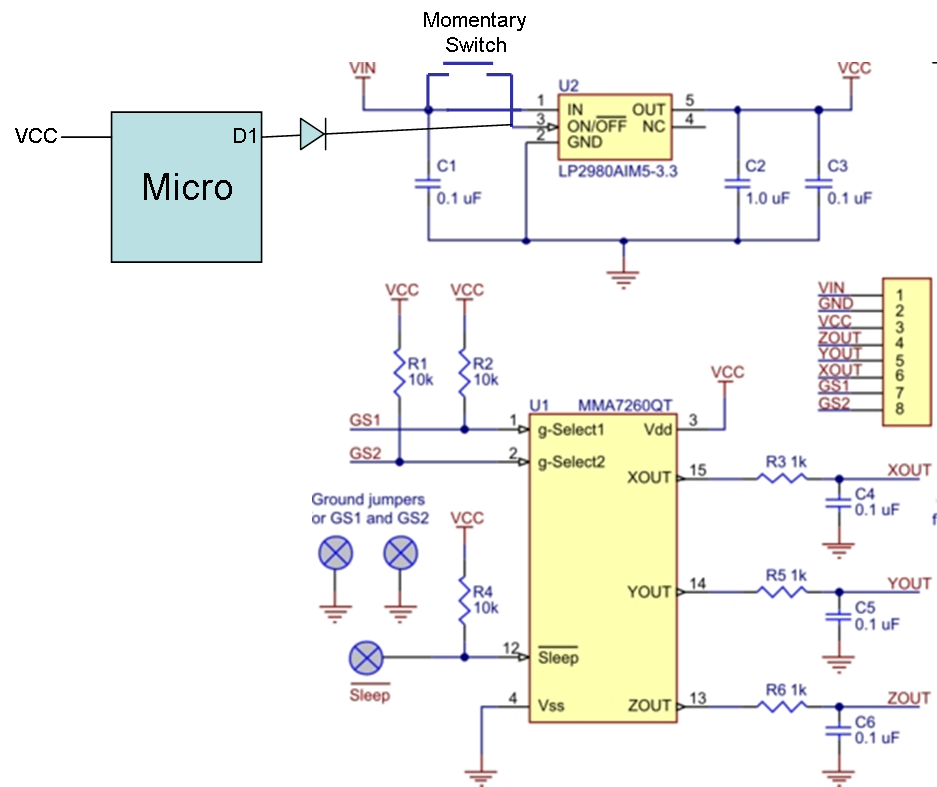
My idea is to modify the circuit to allow a digital power shutoff control. Make the enable pin on the voltage regulator be accessable via a jumper that when on would restore default behavior, but when off would allow connection to a momentary switch and a digital input from a micro controller (see schematic).
It’s definitely great that these MEMs sensors have gotten so cheap, and I’m happy to hear you like the integrated regulator.
I don’t understand your RC filter question. Did you get a board that had different values for the resistors or caps? Or are you getting a different level of noise on different axes?
For the regulator enable pin, you might need to do a bit more so that the pin isn’t left floating. I don’t know what your circuit will do when power is applied, and I’m not sure the microcontroller will be able to turn the regulator off with that diode there. It looks like the layout of the board will allow you to cut the trace to pin 3, so if you try it, I am interested in the results.
The RC filter differences I was referring to are the resistors on pins 15, 14, 13. The values are 3.1, 5.1, and 6.1 respectively. The cutoff freq for an RC filter is 1/(2 pi R C). So the cutoff freqs are
co_x = 1 / ( 6.28 x 3.1e3 x .1e-6) ~ 513 Hz,
co_y = 1 / ( 6.28 x 5.1e3 x .1e-6) ~ 312 Hz,
co_z = 1 / ( 6.28 x 6.1e3 x .1e-6) ~ 260 Hz.
The datasheet on the LP2980 says that 1.6 V is required on the enable pin to enable the device. I may not be able to get that with the diode there. The alternatives are to go straight into the pin if VIN is low enough on the unregulated source, otherwise use an opto isolator. It looks like demo boards are available for that part. If I can find one, I’ll let you know how any experiments work out.
The filters for the three channels should all have 1k resistors. When you see something like R3 1k in the schematic, it means that the resistor is designated R3 and it has a value of 1k, not that it’s a resistor with the value 3.1k.
Doh! Makes sense. But that makes the bandwidth around 1.5KHz, which implies sampling at at least 3KHz! Can’t quite close the loop on that digitally filtering 3 axes. Thanks for pointing me in the right direction.