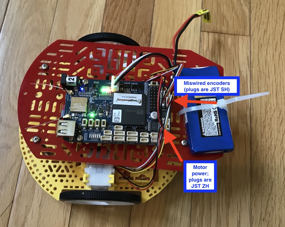
This post is about the “Magnetic Encoder Pair Kit for Mini Plastic Gearmotors”, product #1523. I purchased a Romi chassis kit, as shown in the photo below, and added a second deck to it by cannibalizing my Magician Chassis. The encoders are connected to a Beaglebone Blue controller, which has 4 dedicated connectors for encoders.
I am running the latest Debian “IoT” image on the Beaglebone. It is fully updated. I am able to log in to the Beaglebone over ssh because it is connected to my network by wifi. From there, I can execute the script “rc_test_encoders”. The script shows no changing output when I move either wheel back and forth gently. On investigating, and looking again at the pinouts for the Beaglebone’s encoder plugs, it turns out that I miswired both of my encoder connections. GND is actually wired to “encoder B” and VCC is actually wired to “encoder A”. The encoder “out B” is connected to GND on the Beaglebone Blue, and encoder “Out A” is connected to 3.3v on the Beaglbone Blue.
My question is, did I ruin my encoders by miswiring them? Please note that on the Beaglebone blue, the encoder connectors are in the form of JST SH housings. So I cannot simply try to reverse the plug. The connectors are keyed. I thought of prying the encoder connector housing off the Beaglebone and turning it around, which would change the orientation of the keyway, but I’m not sure that can be done, or if it can, whether the pins will still mate properly with the connectors.
This was a good lesson for me in being more careful when I read and interpret schematic diagrams for Beaglebone Blue. I still don’t quite understand how the pins are oriented on the actual PCB for JST connectors.
Thanks a ton
Bob