Hi. I have been working now with MinImu9 v5 for some years, and recently i came across a problem. I was writing an arduino program to read data from sensors (Force sensors and IMU sensor), using a Adafruit Feather M0 WiFi board. The board would read the sensor data at a frequency of 100Hz and send data in the form of a UDP packet to my PC for further data processing, visualization and saving. Lately i am having problems with data from the MiniImu9 v5, the IMU works and i am getting raw accel, gyro and mag data from the board, but i think i have a problem with the data not being correct. The accel and gyro measurements quickly reach max values (-/+ 32766) while i am moving the sensor in small increments. I have a identical system, with identical electrical components from 2018 and the IMU does not have this problem. I have tried everything, swapped out the IMU, the Adafruit board, passive componentc (resistor and capacitor, OpAMP), and the IMU is reporting almost the same values, it reaches saturation (don’t know if this is the right word, it reaches the sensor MAX reading) with small movements. The MinImu is connected in the following manner to my Adafruit board: SCL - SCL, SDA - SDA, GND - GND, 3V - Vin. The attached file contains the output from the LSM6 example Serial sketch, you can see that gyro readings are reaching MAX values, this is done when holding the IMU and rotating it slowly (approx. 1s for 90° of rotation).
Is this normal operation of the sensor, am i doing something wrong? I am starting to suspect the updated libraries for Wire, SPI and SAMD (by Adafruit), because the system i have from 2018 was programmed using the library versions from then. If i apply the same code using newer Arduino IDE version and library versions (an identical system from 2018, i have 3 of them), the old system with the code uploaded by the older libraries does not cause IMU sensor saturation, while the same code uploaded to an identical system using newer Arduino IDE software and library versions cause the sensor to report MAX values when performing small movements. I also tried A LOT of different library versions and combinations to upload the code, nothing resloved my problem.
MinImu9-problem.txt (10.0 KB)
Thanks for any input.
Br
David
Hello, David.
Can you confirm the sample output you posted is from running the unmodified example program, Serial.ino, from our LSM6 library?
It sounds like your MinImu-9 was working at some point and still works if you revert some of your software to older versions. Can you specify what versions of your libraries cause it to work as expected? You also mentioned swapping hardware around. How many different MinIMUs did you try, and can you post some pictures of your setup? Could you also provide some sample output from a good setup?
- Patrick
Hi Patrick,
Yes, the output is from the Serial.ino LSM6 Example sketch, which is unmodified, only uploaded to my board. I don’t know the exact versions of the libraries/boards/Arduino, as this was 2018, and i was “smart” enough to think this would not have an effect. I have info for the following library versions i used:
-WiFi101: 15.2.0
-LSM6 and LIS3MDL: 1.0.0
-SAMD boards (by polulu): 1.3.0 or 1.6.2
-No info for Arduino IDE and corresponding library versions: wire.h, SPI.h, WiFiUdp.h
I tried three different MinIMUs, with three different Adafrit boards.
As for the sample output, i cannot get the sample output from the “good” 2018 system as i uploaded the code from 2018 to my “good” system using updated Arduino IDE and libraries/boards, and the IMU started to show the same odd data than my newest 2022 system that is basically identical, just built this year. From 2019 to now i wasn’t doing anything with this, now i started to continue the project, i just updated the Arduino IDE and libraries/boards, uploaded the same code to the system that was previously working OK, and now the IMU readings get saturated with small movements. So i am suspecting the updated Arduino IDE, libraries and/or boards. Something is causing this and i have yet to identify the culprit.
Br
David
Do you have a different microcontroller, like an Arduino Uno, that you can try the example program with? What happens if you configure the sensors to measure in its broader sensitivity ranges; does it still report values at or near the maximum?
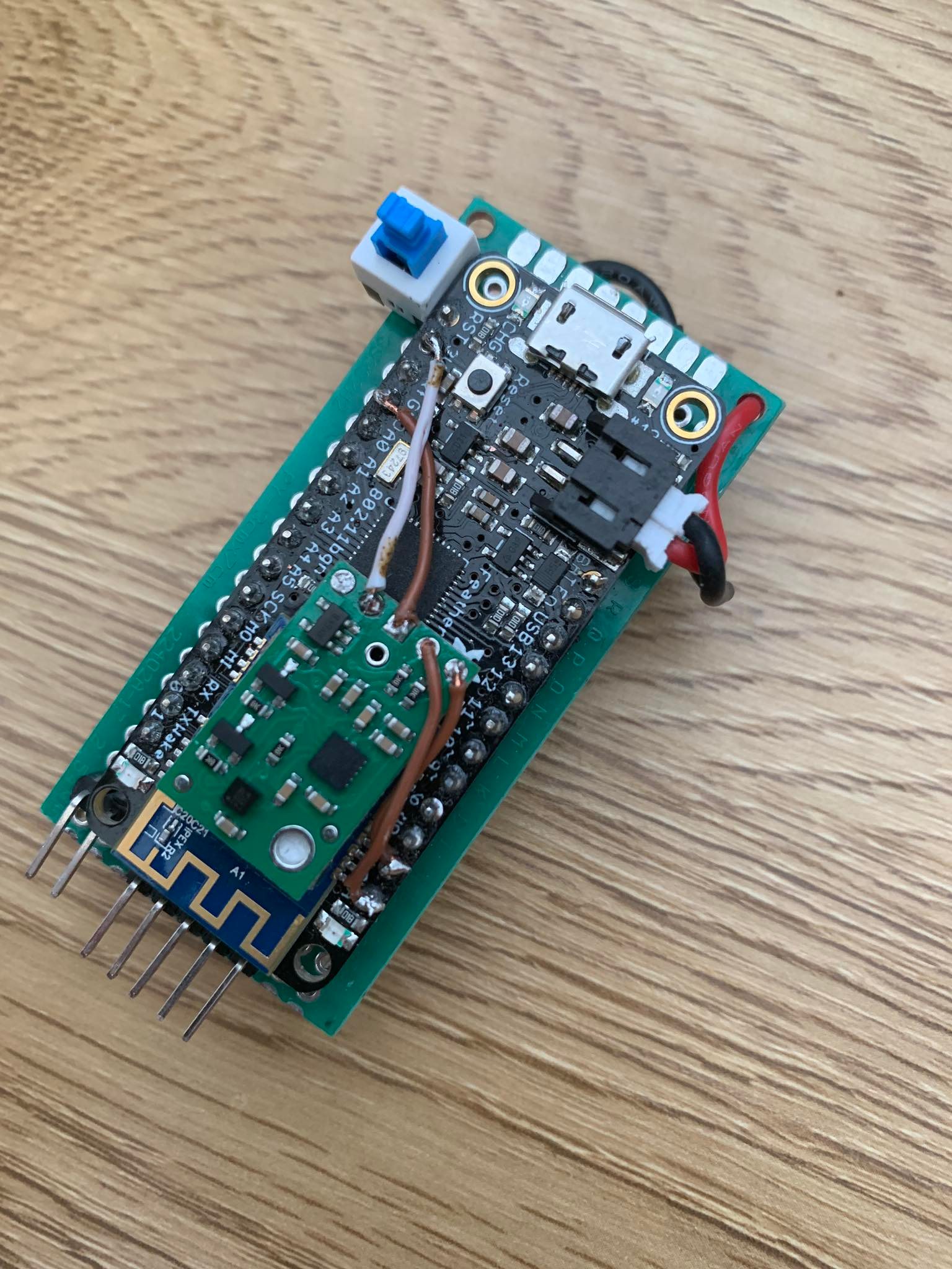
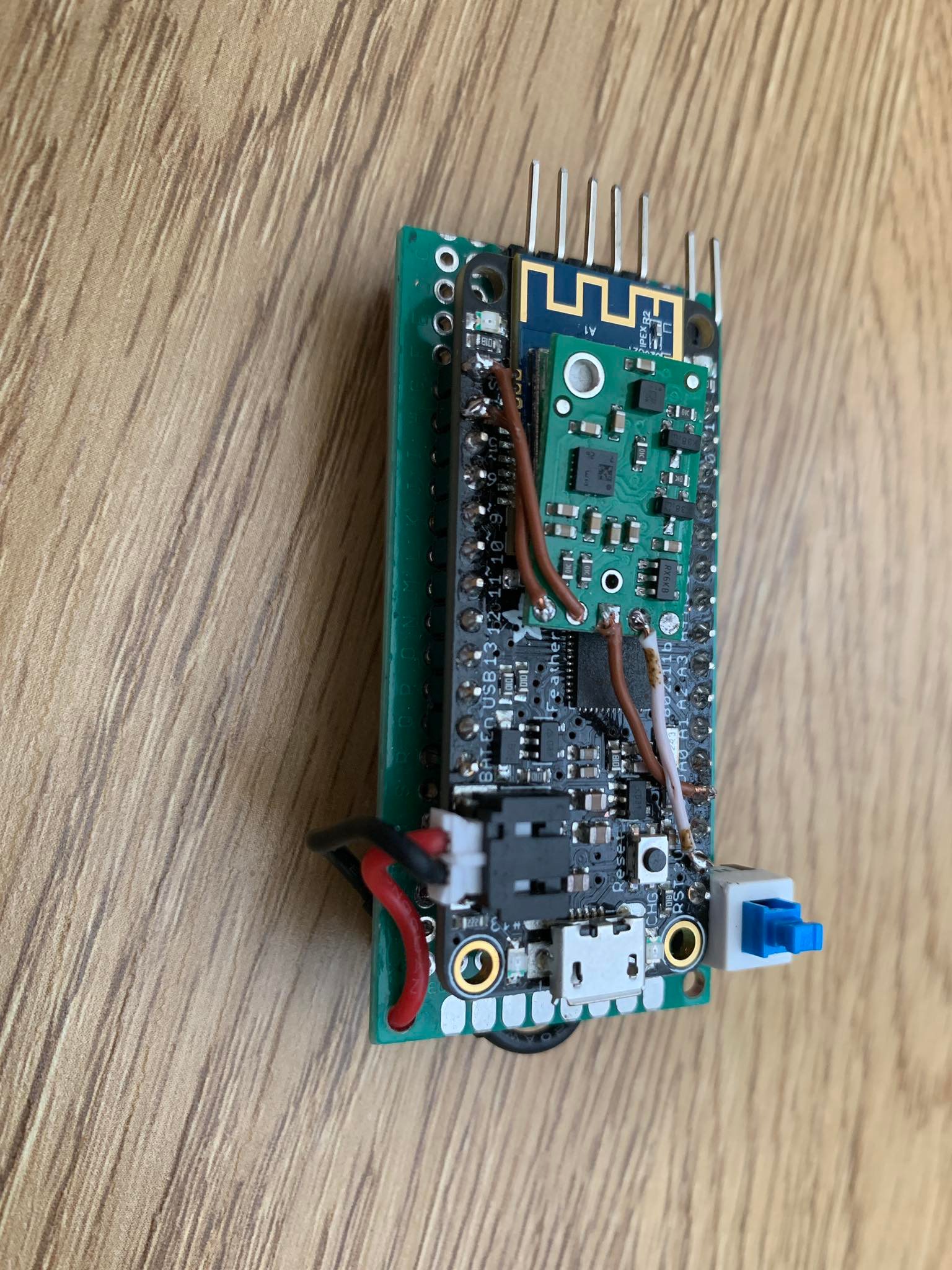
Also, it would still be useful if you could post some pictures of your MinIMU boards and the overall setup.
- Patrick
I have an olimex esp32-poe-iso also, i will try with that.
How do i configure the sensor to measure in broader sensitivity ranges?
Pictures from my setup attached.
Hi Patrick, the behavior of the Olimex board when executing the unchanged LSM6 Example sketch is the same, the IMU reports saturation while doing small movements. Pasted is the output. You can see that the Gyro X value reports saturation while doing relatively small movements. Also i am posting a video for you to maybe get a better understanding of the situation.
MinImu9-problem_Olimex.txt (5.2 KB)
From your video, you seem to be making those movements fairly quickly, so it doesn’t seem especially unusual for the gyro output to be saturating. (The default full scale is 245 dps.) You can reconfigure the gyro’s sensitivity range by changing the FS_G bits in the CTRL2_G register (see the LSM6DS33 datasheet for details). To do that (while keeping the output data rate at the library default of 1.66 kHz), you can add a line like this to the end of your setup function:
imu.writeReg(LSM6::CTRL2_G, 0x8c);
These values for the second argument will set the following sensitivities:
- 0x84 for 500dps
- 0x88 for 1000dps
- 0x8c for 2000dps
You might also consider adding a line like this to confirm that you wrote to the register successfully:
Serial.println(imu.readReg(LSM6::CTRL2_G), HEX);
Please let me know if the gyro values still saturate while operating in those other sensitivity modes.
- Patrick
Hi Patrick, i reconfigured the Gyro and the Accel sensitivity range to measure in the max values (Accel: 16G, Gyro: 2000dps). Now, the IMU is reading correct values (in my PC labview code), i confirm that by placing the IMU on a level surface (with componenct facing upward), and the Accel readings are reading approx. 0 in the X and Y plane, and 1 in the Z plane, which means the Accel is reading the gravitational force of 1G correctly when no other forces are applied to it. These values are derived from my PC LabView code, which translate the analog values of the sensor to G force for Accel and DPS angular velocity. Would i have to also fix some registers for the magnetometer?
Thank you very much for the help. In the words of The Foo Fighters: “There goes my hero” 
Br
David
I am glad to hear that you got it working!
I would not expect you to have to change anything about the magnetometer unless you notice distortions from those readings saturating.
By the way, you might consider trying to lower the accelerometer and gyro full scales to one of the intermediate ranges if maximizing resolution is important.
- Patrick