I’ve been running your AHRS code with the MinIMU 9 v5 at 400kHz I2C speeds on an Arduino Mega2560 with no issues, but I recently switched over to an Arduino MKR1000 where, at the fast speed, the yaw spins at about 1 rotation every 3-5 seconds when the IMU is stationary. If I reduce the I2C speed to 100kHz, things are fine again. Have you seen this before?
FYI, I shortened the wires to the MCU to 3" from about 7" as a part of the transition to the MKR1000, and to test if that caused the problem I fell back to the Mega2560, but it still ran properly at the fast speed. I also begin each test with compass calibration and give the DCM algorithm 5 seconds to settle down. Could it be the shift to 3.3V? Or the additional 4.7k I2C pullups on the MKR1000?
We have not seen the behavior you’re seeing nor have we heard of others encountering a similar issue. I tried reproducing the problem using an AltIMU-10 v5 with an Arduino MRK1000 and the clock frequency set to 400kHz, but the program ran as expected. Can you post your calibration values for your MinIMU sensor? Can you post an attachment containing your modified version of the MinIMU-9 + Arduino AHRS program?
Thanks for checking it out. I gather calibration values each time I power up because I noticed that they varied from place to place (sometimes within a few feet), so you will see in my attached test code that it will gather mins and maxes until you send it a serial character. While it’s gathering mins and maxes, I rotate the MinIMU to the left and right a few times.MinIMU9AHRSjlo.zip (6.3 KB)
I ran your code on the Arduino MKR1000 and did not see the behavior similar to what you described. I even ran your code on an Arduino Uno using the same AltIMU-10 v5 sensor board, but did not notice anything substantially different in the readings compared to the Arduino MKR1000 readings. Can you run your code again on the Arduino MKR1000, but this time try calibrating your MinIMU by imagining the board is the tip of a paintbrush and you are trying to paint the inside of a sphere? Are there any differences in your setup between the Arduino Mega 2560 and Arduino MKR1000? Can you post pictures showing how everything is connected in your system?
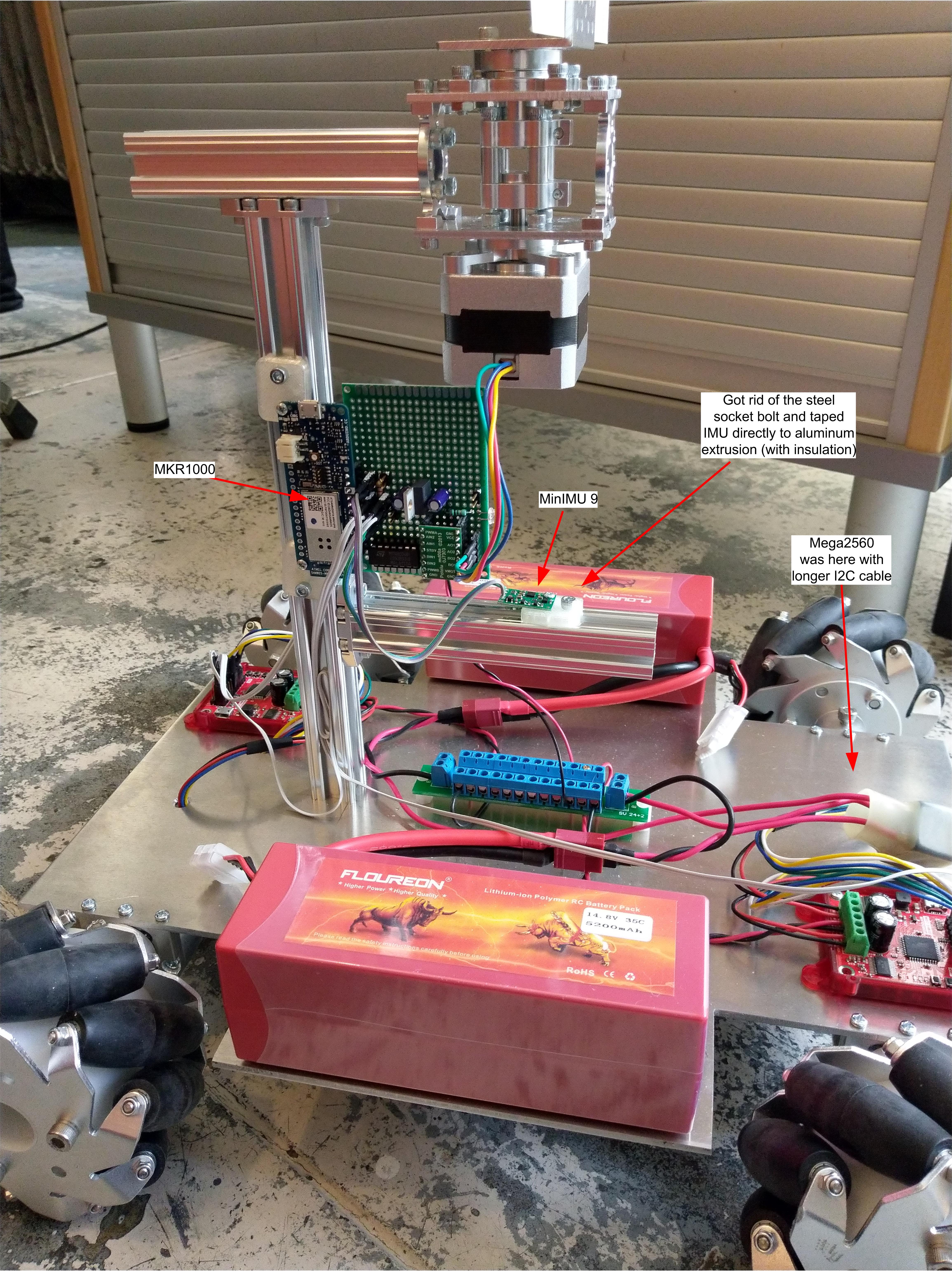
I’m hoping to do the calibration with the robot itself, so moving the sensor in the way you suggest is impossible without adding an arm. There are no differences in set up (that I can think of) except for the length of the I2C cable, v+, and I2C pullups on the MKR1000. No other devices are sharing the I2C bus. Here’s a picture:
Oh but there is one other difference: with the Mega2560 I was driving the stepper motor with a SparkFun EasyDriver, but in this new circuit you can see I’m using your TB6612FNG carrier and managing the PW and microstepping myself. That said, for the MKR1000 tests, I tried de-energizing the stepper just to see if the motor’s magnetism was confusing the MinIMU but nothing changed. That was before I discovered that dropping back to 100khz I2C clocking fixed things.
Can you remove the Arduino MKR1000 and MinIMU boards from your robot and see if you get the same behavior? If you try stronger pull-up does that make the readings better? Can you use an oscilloscope to inspect the activity on the SCL and SDA lines and see if they match what you would expect? Also, is there a particular reason why you want to have I2C operate in fast mode?
Thanks for these great suggestions (not sure why they didn’t occur to me!). Removing the MKR1000 from the robot and running my test code at 400khz produces much more stable output, although there is still more drift than at 100khz. On the Mega2560, just eyeballing the signals on a scope, SDA has more noise in the v+ state and CLA has a slower rise time, which is consistent with the fact that it has 10k pullups vs the MKR1000’s 4.7k pullups. Therefore, no, I didn’t try stronger pullups as the MKR1000 already has stronger ones.
Honestly, no, I don’t have a reason to want to run at 400khz except that the datasheet said it was possible. I was just surprised that dropping back to 100khz made the spin go away and am curious why. But the fact that things run better when they’re not attached to the robot suggests to me that the I2C speed correlation might be just another symptom, not the cause–what do you think? Adding to the confusion, there have been a few times that I’ve observed the MinIMU yaw to rotate once slowly even at 100khz I2C speeds, so even the speed reduction is not fully addressing the issue.
It’s not clear to us why your readings are sometimes affected. It seems like the issue might be something interfering with either the I2C communications or the magnetometer readings. It is possible for the non-magnetized metal of the motor to affect the magnetic field (soft iron distortions). You might also consider the environment you are in; please note things like power conduits and rebar under the concrete can generate magnetic fields which could be causing interference. You could try troubleshooting by making minor changes in your setup(s), such as by moving the stepper motor closer or farther from the sensor and seeing if/how the readings change.
Here’s one last strange data point: I noticed that I was calling Compass_Init() twice, once to begin my calibration routine, and again as a side-effect of calling IMU_Init(). After I commented out the 2nd one, I was able to run I2C at 400khz on the MKR1000 without any issues! I don’t see anything in the LIS3MDL data sheet that would explain that change in behavior, and the fact remains that I don’t have this problem on a Mega2560, Maybe it’s related to mcu execution speed, I dunno. Anyway, thanks again for your time and expertise.