Here it is.
MinIMU-9-Arduino-AHRS-master.zip (36.1 KB)
I spent a while looking at your code and eventually realized the reason it wasn’t working: Whenever an interrupt on the ATmega328 occurs, the global interrupt enable bit is cleared (disabled). Usually, the interrupt routine executes and then global interrupts are enabled again automatically when you return from the interrupt routine. However, this caused a problem with what you were doing, because global interrupts were disabled when the Timer1 interrupt fired, and that prevented the Wire library (which is used to communicate with the sensors on the IMU) from working since it uses the TWI interrupt to do things.
Fortunately, the solution is simple: you can just call sei() inside the Timer1 callback to enable nested interrupts. I tried putting it here and that seemed to fix the problem:
    ...
    sei(); // enable nested interrupts so TWI interrupt works
    // *** DCM algorithm
    // Data adquisition
    Read_Gyro();   // This read gyro data
    Read_Accel();     // Read I2C accelerometer
    ...
- Kevin
Its working perfect here.
Thank you very much for the help and the explanation for my problem.
Could you tell me how to set this
values please? I am using Arduino AHRS code.Here are the init functions:
gyro:
void Gyro_Init()
{
  gyro.init();
  gyro.writeReg(L3G_CTRL_REG1, 0x0F); // normal power mode, all axes enabled, 100 Hz
  gyro.writeReg(L3G_CTRL_REG4, 0x20); // 2000 dps full scale
}
accel:
void Accel_Init()
{
  compass.init();
  if (compass.getDeviceType() == LSM303DLHC_DEVICE)
  {
    compass.writeAccReg(LSM303_CTRL_REG1_A, 0x47); // normal power mode, all axes enabled, 50 Hz
    compass.writeAccReg(LSM303_CTRL_REG4_A, 0x08); // high resolution output mode
    compass.writeAccReg(LSM303_CTRL_REG4_A, 0x20); // 8 g full scale: FS = 10 on DLHC
  }
  else
  {
    compass.writeAccReg(LSM303_CTRL_REG1_A, 0x27); // normal power mode, all axes enabled, 50 Hz
    compass.writeAccReg(LSM303_CTRL_REG4_A, 0x30); // 8 g full scale: FS = 11 on DLH, DLM
  }
}
compass:
void Compass_Init()
{
  compass.writeMagReg(LSM303_MR_REG_M, 0x00); // continuous conversion mode
  // 15 Hz default
}Hello.
Can you explain exactly what you’re having trouble with? The datasheets for the sensors describe the settings and the registers used to configure them, and our libraries provide generic functions for writing and reading registers in the devices. If you have a specific question about something you don’t understand, we can try to answer it for you. Otherwise, if you are having trouble understanding the datasheets or the library code in general, you could try asking for help from someone nearby with electronics experience.
-Jon
[quote=“JonathanKosh”]Hello.
Can you explain exactly what you’re having trouble with? The datasheets for the sensors describe the settings and the registers used to configure them, and our libraries provide generic functions for writing and reading registers in the devices. If you have a specific question about something you don’t understand, we can try to answer it for you. Otherwise, if you are having trouble understanding the datasheets or the library code in general, you could try asking for help from someone nearby with electronics experience.
-Jon[/quote]
Hi, i am having trouble ,like i sayed, with setting the sensors to a specific frequency and sensitivity.If there was someone with electronic experience nearby i wouldn’t be writing my problem in a forum.
In order to determine which value to write to each register, you’ll need to use the appropriate table that explains what the bits in the register do so you can build a value that represents all of the settings you want.
For example, we can look at Tables 19, 20, and 21 inside the gyro datasheet, which describe the CTRL_REG1 register. Values assigned to the DR1, DR0, BW1, BW0 bits determine the output data rate (ODR) and frequency cut-off as described in Table 21. So, if you are interested in an ODR of 95 Hz and a cut-off frequency of 12.5 Hz, then DR1, DR0, BW1, and BW0 should be set to 0, 0, 0, and 0, respectively. Then, you can continue to set bits that correspond to the behavior you are interested in. Let’s complete the example by putting the gyro in normal power mode and enabling all axes. To do this, you would want to write a value that corresponds to “00000111”:
DR1	DR0	BW1	BW0	PD	Zen	Xen	Yen
 0	  0	  0	  0	  0	 1	  1     1
“00000111” is 0x07 in hexadecimal, or 7 in decimal. All of those values are valid for the write function:
gyro.writeReg(L3G_CTRL_REG1, 0x07);  // hexadecimal version
gyro.writeReg(L3G_CTRL_REG1, 0b00000111);  // binary version
gyro.writeReg(L3G_CTRL_REG1, 7);  // decimal version
-Jon
Thanks! Just one more question can i break the sensor board if i write a wrong value( i mean a value that cannot be made by the DR1 DR0 BW1 BW0 PD Zen Xen Yen)For example 0b000001112 or 0b00000112?Oh, and by the way why this 0b and 0x is always put in front and why the decimal version doesn’t have 0x or 0b or something?
In your specific example, the Arduino compiler will throw an error when numbers other than zero or one are used with the “0b” prefix, since 2 is not a valid binary digit:
gyro.writeReg(L3G_CTRL_REG1, 0b00000112); // this will not compileAny number starting with “0b” or “B” is interpreted as a binary number by the Arduino compiler, and anything starting with “0x” is hexadecimal. You can read more about the way integer constants are interpreted here.
So I have tried out the latest version of v1.2.2 which supports LSM303 library 2.0.0, however, I have drift in Yaw. (It goes correctly to the right compass direction and gradually goes beyond it further and further).
With the previous version v1.2.1 which supports LSM303 library 1.4.4, there is no problem at all. (I did all the caliberation as guided).
So is anyone experiencing the same problem ? Since the MinIMU-9 AHRS code is pretty much the same, I suspect the major rewrite of LSM303 2.0.0 is not stable, isn’t it ?
I’d appreciate some comments or insights from Kevin or any other Pololu engineer working on this… Thanks. Anh.
Hello,
Are you using the same calibration constants you were using with the older AHRS code and LSM303 library, or did you try running the calibration again with the new library? Which version of the MinIMU-9 and what type of Arduino are you using?
- Kevin
Hi Kevin,
Thanks for your reply during holiday season. Everytime I switch to a different version of LSM303 / AHRS, I re-calibrate the device. I’m using MinIMU-9-v2 and Arduino UNO R3.
I have double-checked this issue and still happening…
Ok, I might have to test it myself when I get a chance (likely later this week). It’s possible I broke something while changing the library for the 2.0.0 release.
- Kevin
I tried running a calibration with the latest LSM303 library (2.0.0) and using the resulting values in the latest AHRS program (1.2.2) and didn’t notice any problems. The compass calibration code and the way the compass data is used in the AHRS didn’t really change from the previous version, so I’m not sure why you’re seeing a difference in behavior.
Do you get significantly different calibration values when you calibrate with the old and new LSM303 libraries? Do you see differences in the yaw behavior if you use the same calibration values on the old and new versions of the AHRS program? How much does the yaw drift? (Is it just a small amount, like 5-10 degrees, or does it drift by a lot more?)
Did you ever change anything in the code (either old or new versions) besides the compass calibration values?
- Kevin
Hi,
I am using the latest AHRS program and calibrated the compass. When I rotate the device on the spot, the returned yaw angle is working just fine with minor drifting. However, when i start to move the device in a translational manner, the yaw angle starts to change alot even if the device is facing the same direction. Is there something that I did it wrongly? Thank you.
Hello.
I am sorry you are having trouble with that sensor. Can you tell me more about how are you moving it? How quickly are you moving it, and are you performing steady movements or accelerating and shaking the IMU a lot? After you stop moving the sensor, does the behavior of the yaw angle return to normal, or does it stay different? If you keep the sensor in place, but rotate it about the other two axes (pitch and roll), does the calculated orientation behave as expected?
By the way, which version of the IMU are you using? Do you have it mounted to anything? If so, how is it mounted? Is there anything nearby (such as magnetic or metal objects or wires carrying large currents) that could be affecting the magnetometer readings?
-Jon
Hello,
Thanks for the reply. I am using Arduino due. I move the sensor pretty slow, along a straight line. In the same time I move my handphone along the same straight line and check the reading on the compass. The sensor has drifted for around 30 degree but my handphone still remains the same. When I stop moving the sensor, the yaw angle does not return to normal. If I keep the sensor in place, and rotate it about the other two axes, the z-orientation is still changing while the readings of x,y orientation are normal(but when I do a 360 rotation on x,y axis the reading only change by 80-90). I am using the minimu9-v2 and it is mounted on a breadboard with its electronic parts facing upwards (I have change the code in the AHRS accordingly). There is nothing nearby other than arduino and wires. (And the handphone is not directly placed beside the sensor).
It seems weird that the calculated yaw is changing because that indicates that the magnetic reading is changing, independent of the calibration. There are a few things you can do that might help me determine what is going on:
Can you take your phone and place it in the exact spot you used for the IMU and move it along the exact path and see if the compass reading changes? (If it does, it might indicate that something is interfering with the magnetic reading like metal in the table or the surface the devices are resting on.)
Can you try running the LSM303 “heading” example (which only uses the magnetometer and accelerometer, not the gyro) and doing the same test and see if the reported heading changes?
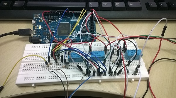
Can you also post a picture that shows your entire setup?
-Jon
Hello,
I just do a thorough test with my phone’s compass, apparently the magnetic field in the room has an average of 40 micro T. And the reading does changing when I move transnational, the angle changes. I tired the heading example as well and the heading does change when I do the same movement. The attachment is the picture of my setup.
Thank you very much for your time ![]()