MiniIMU-9 V3 problems with LSM303D

I’m experimenting with the MiniIMU-9 and i was able to configure and read correctly the data from the gyroscope

However the accelerometer (and the compass as well) doesn’t seem to work properly. The I2C communication seems to work and the device responds correctly when reading the WHO_I_AM register but when I try to configure and read the accelerometer data i only obtain L = 01011111 H = 01111100 for all three axys, with no variation in motion. Also when i read back the CTRL0-CTRL3 i don’t get back the values i configured but slightly different values. Is it broken or something?

I tried a second MiniIMU-9 v3 and still the same. The gyro and the magnetometer work correctly , while the accelerometer shows junk data totally unaffected by motion and shocks…

Probably both are broken…

Hello.

I am sorry you are having trouble with the MinIMU-9. Can you tell me more about how you are trying to read and write to the registers? What device are you using to send the MinIMU signals? If you are using an Arduino, have you tried using our LSM303 library? If you are not using an Arduino, can you post the code you are using?

-Jon

Hi! I’m using a PIC18F2680 instead of arduino with picbasic code.

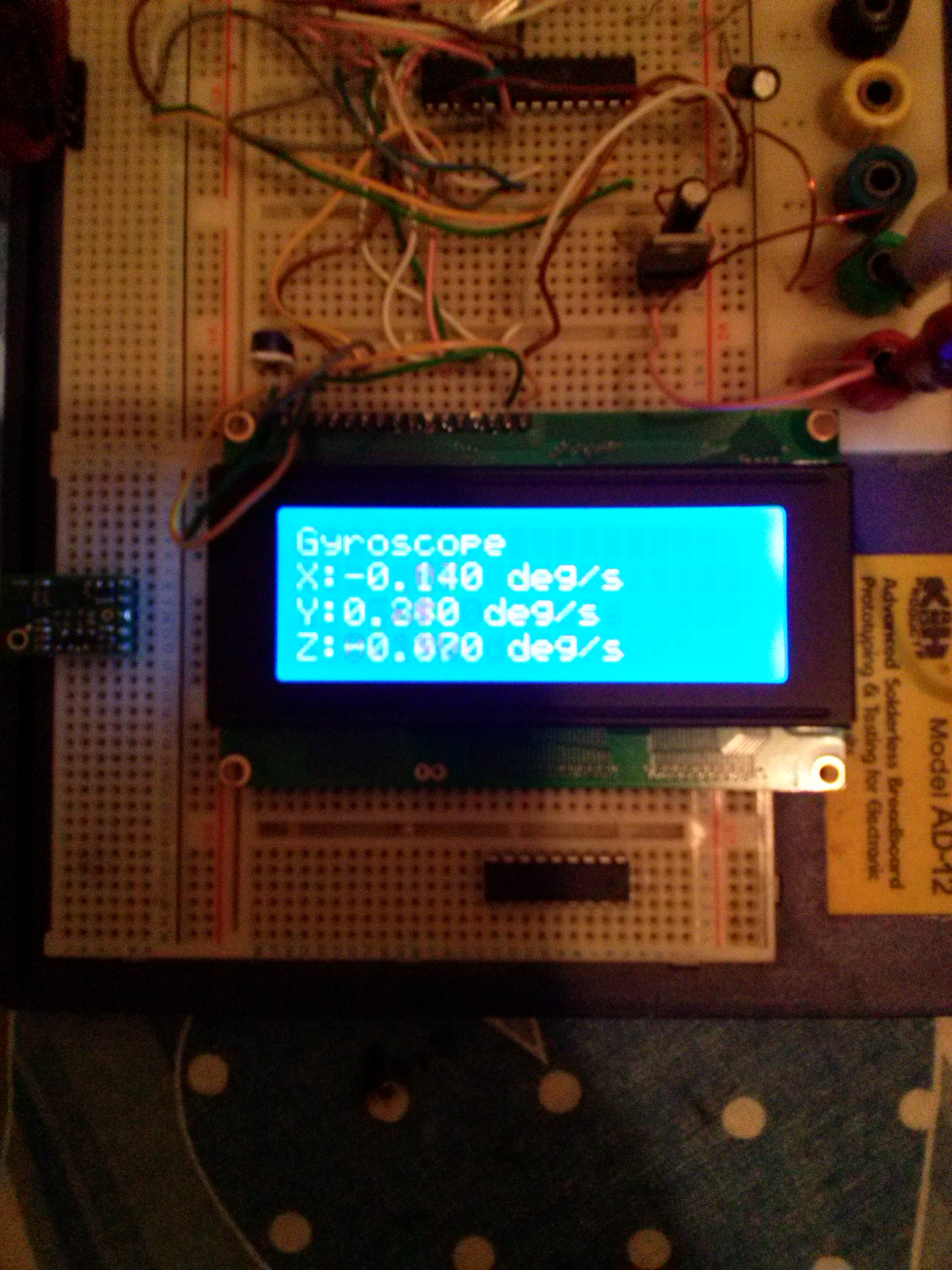
Gyroscope response (offset subraction): (excellent)


Accelerometer: (fail)


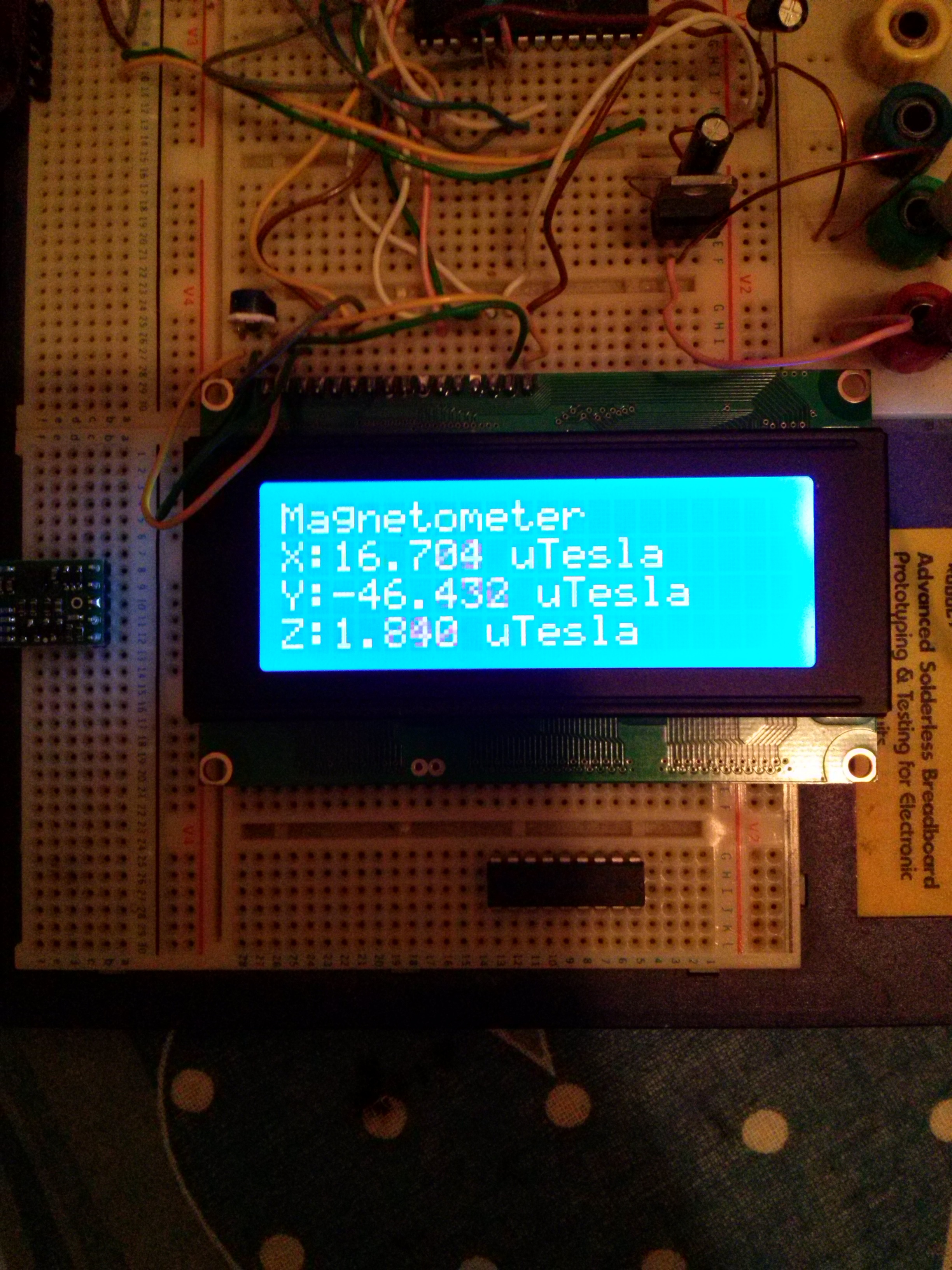
Magnetometer: (excellent)


Here there are my register settings:

'****************************************************************
'***   ALIASES                                                ***
'****************************************************************

' SLAVE addresses
 Symbol MEMS_MagnetAccel_R             = %00111011 'SA0 High
 Symbol MEMS_Gyro_R                    = %11010111 'SA0 High
 Symbol MEMS_MagnetAccel_W             = %00111010 'SA0 High
 Symbol MEMS_Gyro_W                    = %11010110 'SA0 High
 
' Generic symbols
 Symbol GX                             = 0
 Symbol GY                             = 1
 Symbol GZ                             = 2
 Symbol WHO_AM_I                      = $0F
 
' gyro sub-addresses
 Symbol GYRO_CTRL1                     = $20
 Symbol GYRO_CTRL2                     = $21
 Symbol GYRO_CTRL3                     = $22
 Symbol GYRO_CTRL4                     = $23
 Symbol GYRO_CTRL5                     = $24
 Symbol GYRO_OUT_X_L                   = $28
 Symbol GYRO_OUT_X_H                   = $29
 Symbol GYRO_OUT_Y_L                   = $2A
 Symbol GYRO_OUT_Y_H                   = $2B
 Symbol GYRO_OUT_Z_L                   = $2C
 Symbol GYRO_OUT_Z_H                   = $2D
 Symbol GYRO_LOW_ODR                   = $39 
 
' accel and magnetometer sub-addresses
 Symbol ACCEL_CTRL0                     = $1F
 Symbol ACCEL_CTRL1                     = $20
 Symbol ACCEL_CTRL2                     = $21
 Symbol ACCEL_CTRL3                     = $22
 Symbol ACCEL_CTRL4                     = $23
 Symbol ACCEL_CTRL5                     = $24
 Symbol ACCEL_CTRL6                     = $25
 Symbol ACCEL_CTRL7                     = $26
 Symbol ACCEL_OUT_X_L                   = $28
 Symbol ACCEL_OUT_X_H                   = $29
 Symbol ACCEL_OUT_Y_L                   = $2A
 Symbol ACCEL_OUT_Y_H                   = $2B
 Symbol ACCEL_OUT_Z_L                   = $2C
 Symbol ACCEL_OUT_Z_H                   = $2D
 Symbol MAGN_OUT_X_L                    = $08
 Symbol MAGN_OUT_X_H                    = $09
 Symbol MAGN_OUT_Y_L                    = $0A
 Symbol MAGN_OUT_Y_H                    = $0B
 Symbol MAGN_OUT_Z_L                    = $0C
 Symbol MAGN_OUT_Z_H                    = $0D
 
  
'gyro configuration 
 Symbol GYRO_SENSITIVITY             = 70 '0.07 dps/s/LSB
 Symbol GYRO_SENS_DIVIDER            = 1 '0.07 dps/s/LSB
 Symbol GYRO_2SCOMPLEMENT_MAX        = $FF00
 Symbol GYRO_CTRL1_VALUE             = %00001111 'DR1-DR0 = 00/BW1-BW0 = 00/PD = 1/
                                                 'Zen = 1/Yen = 1/Zen = 1   , data rate 100Hz
 Symbol GYRO_CTRL2_VALUE             = %00100011 'EXTRen = 0/LVRen = 0/HPM1-HPM0 = 00/  'high pass filter normal
                                                 'HPCF3-HPCF0 = 0011      ' 1 Hz High pass filter cut off freq
 Symbol GYRO_CTRL3_VALUE             = %00000000 'INT1-IG = 0/INT1-BOOT = 0/H_LACTIVE = 0/PP_OD = 1
                                                 'INT2_DRDY = 0/INT2_FTH = 0/INT2_ORun = 0/INT2_Empty = 0
 Symbol GYRO_CTRL4_VALUE             = %00100000 'BDU = 0/BLE = 0/FS1-FS0 = 10/IMPen = 0/ST2-ST1 = 00/ SIM = 0 
                                                 '2000 dps full scale
 Symbol GYRO_CTRL5_VALUE             = %10010000 'BOOT = 1/FIFO_EN = 0/StopOnFTH = 0/HPen = 1/IG_Sel1-IGSel0 = 00
                                                 'OUTG_Sel1-OUTGSel0 = 00                                                                                 
 Symbol GYRO_LOW_ODR_VALUE           = %00000000 '-/-/DRDY_HL = 0/-/I2C_dis = 0/SW_RES = 0/LOW_ODR = 0
                                                                                                                                             
'accel & magnetometer configuration 
 Symbol ACCEL_SENSITIVITY             = 122 '0.122 mG/LSB
 Symbol ACCEL_2SCOMPLEMENT_MAX        = $FF00
 Symbol MAGN_2SCOMPLEMENT_MAX         = $FF00
 symbol MAGN_SENSITIVITY              = 160 ' 0.160 mgauss / LSB

 Symbol ACCEL_CTRL0_VALUE             = %00000000 'BOOT = 1/FIFO_EN = 0/FTH_EN = 0/0/0/HP_Click = 0/HPIS1 = 0/HPIS2 = 0
 Symbol ACCEL_CTRL1_VALUE             = %01100111 'ADDR3-ADDR0 = 0110/DBU = 0/AZEN = 1/AYEN = 1/AXEN = 1
                                                  ' 100 Hz data rate, all channels elabled
 Symbol ACCEL_CTRL2_VALUE             = %11001000 'ABW1-ABW0 = 11/AFS2-AFS0 = 001/0/AST = 0/SIM = 0
                                                  '50 Hz filter bandwith , 4g sensitivity
 Symbol ACCEL_CTRL3_VALUE             = %00000000 'INT1_BOOT = 0/INT1_Click = 0/INT1_IG1 = 0/INT1_IG2 = 0/INT1_IGM = 0
                                                  'INT1_DRDY_M = 0/INT1_DRDY_M = 0/INT1_EMPTY = 0
 Symbol ACCEL_CTRL4_VALUE             = %00000000 'All interrupts disabled
 Symbol ACCEL_CTRL5_VALUE             = %11110100 'TEMP_EN = 1/M_RES1-M_RES0 = 11/M_ODR2-M_ODR0 = 101/ IRQ non latched
                                                  '100Hz magnetometer data rate
 Symbol ACCEL_CTRL6_VALUE             = %00100000 'MFS1-MFS= 10 magnetic full scale set to 4gauss
 Symbol ACCEL_CTRL7_VALUE             = %10000000 'AHPM1-AHPM0 = 00/AFDS = 0/T_ONLY = 0/MLP = 0/MD1-MD0 = 00


' pin assignements
SYMBOL I2C_DATAPIN                   = PORTB.1    ' data assigned to PORTB.1
SYMBOL I2C_CLOCKPIN                  = PORTB.0    ' clock assigned to PORTB.0
 
 
'****************************************************************
'***   I/O PORT ASSIGNMENTS                                   ***
'****************************************************************

TRISB.1 = 0
TRISB.0 = 0

This is the part that reads and translates the signals from 2’s complement to fixed point

******************************************************************************
'********** M_READGYRO_RAW -> vector M_Gyro_RAW[WORD]
'********** this subroutine reads the on-board IMU gyroscope
'********** 
'******************************************************************************
M_READGYRO_RAW: 
 
 I2CREAD I2C_DATAPIN,I2C_CLOCKPIN,MEMS_Gyro_R,(GYRO_OUT_X_L+$80),[STR M_b\6]

 for M_s1 = 0 to 4 step 2
  M_Gyro_RAW[M_s1/2] = M_b[M_s1] + M_b[M_s1+1] * $FF
 next
return


'******************************************************************************
'********** M_READGYRO -> vector M_Gyro[LONG] , angle rate in mdegrees/s
'********** this subroutine reads the on-board IMU gyroscope
'********** 
'******************************************************************************
M_READGYRO: 
  I2CREAD I2C_DATAPIN,I2C_CLOCKPIN,MEMS_Gyro_R,WHO_AM_I,[M_s1]
 gosub M_READGYRO_RAW:
   
 for M_s1 = 0 to 2 
   if M_Gyro_RAW[M_s1] > 32768 then ' sign negative  2's complement value  
   M_Gyro[M_s1] = (-(GYRO_2SCOMPLEMENT_MAX - M_Gyro_RAW[M_s1]) - M_Gyro_RAW_OFFSET[M_s1]) * GYRO_SENSITIVITY / GYRO_SENS_DIVIDER    
  else
   M_Gyro[M_s1] = (M_Gyro_RAW[M_s1] - M_Gyro_RAW_OFFSET[M_s1]) * GYRO_SENSITIVITY / GYRO_SENS_DIVIDER    
  endif
 next

return


'******************************************************************************
'********** M_CONFIGGYRO 
'********** configurates the Gyroscope device
'********** 
'******************************************************************************
M_CONFIGGYRO: 
 
  I2CWRITE I2C_DATAPIN,I2C_CLOCKPIN,MEMS_Gyro_W,(GYRO_CTRL1),[GYRO_CTRL1_VALUE]
  I2CWRITE I2C_DATAPIN,I2C_CLOCKPIN,MEMS_Gyro_W,(GYRO_CTRL2),[GYRO_CTRL2_VALUE]
  I2CWRITE I2C_DATAPIN,I2C_CLOCKPIN,MEMS_Gyro_W,(GYRO_CTRL3),[GYRO_CTRL3_VALUE]
  I2CWRITE I2C_DATAPIN,I2C_CLOCKPIN,MEMS_Gyro_W,(GYRO_CTRL4),[GYRO_CTRL4_VALUE]
  I2CWRITE I2C_DATAPIN,I2C_CLOCKPIN,MEMS_Gyro_W,(GYRO_CTRL5),[GYRO_CTRL5_VALUE]  
  I2CWRITE I2C_DATAPIN,I2C_CLOCKPIN,MEMS_Gyro_W,(GYRO_LOW_ODR),[GYRO_LOW_ODR_VALUE]   
  
  gosub M_READGYRO:
  
return


'******************************************************************************
'********** M_CONFIGGYRO 
'********** calculates the gyroscope offset
'********** 
'******************************************************************************
 
M_CONFIGGYROOFFSET: 
   ' offset calibration

  for M_s0 = 0 to 2
   M_Gyro_RAW_OFFSET[M_s0] = 0
   for M_s2 = 0 to 255
    gosub M_READGYRO_RAW:
    M_Gyro_RAW_OFFSET[M_s0] = M_Gyro_RAW_OFFSET[M_s0] + M_Gyro_RAW[M_s0] 
    pause 2
   next M_s2 
   M_Gyro_RAW_OFFSET[M_s0] = M_Gyro_RAW_OFFSET[M_s0] / 256
  if M_Gyro_RAW_OFFSET[M_s0] > 32768 then ' sign negative  2's complement value  
   M_Gyro_RAW_OFFSET[M_s0] = -(GYRO_2SCOMPLEMENT_MAX - M_Gyro_RAW[M_s0])   
  else
   M_Gyro_RAW_OFFSET[M_s0] = (M_Gyro_RAW[M_s0] )  
  endif
  next M_s0


return


'******************************************************************************
'********** M_READACCEL_RAW -> vector M_Accel_RAW[WORD]
'********** this subroutine reads the on-board IMU accelerometer
'********** 
'******************************************************************************
M_READACCEL_RAW: 
 
 I2CREAD I2C_DATAPIN,I2C_CLOCKPIN,MEMS_Magnetaccel_R,(ACCEL_OUT_X_L+$80),[STR M_b\6] 
 for M_s1 = 0 to 4 step 2
  M_Accel_RAW[M_s1/2] = M_b[M_s1] + M_b[M_s1+1] * $FF
 next
return


'******************************************************************************
'********** M_READACCEL -> vector M_Accel[LONG] , acceleration in g
'********** this subroutine reads the on-board IMU accelerometer
'********** 
'******************************************************************************
M_READACCEL:
 I2CREAD I2C_DATAPIN,I2C_CLOCKPIN,MEMS_MagnetAccel_R,WHO_AM_I,[M_s1]
 gosub M_READACCEL_RAW:
   
 for M_s1 = 0 to 2 
   if M_Accel_RAW[M_s1] > 32768 then ' sign negative  2's complement value  
   M_Accel[M_s1] = -(ACCEL_2SCOMPLEMENT_MAX - M_Accel_RAW[M_s1])  * ACCEL_SENSITIVITY   
  else
   M_Accel[M_s1] = M_Accel_RAW[M_s1] * ACCEL_SENSITIVITY 
  endif
 next

return
                
'******************************************************************************
'********** M_READMAGN_RAW -> vector M_Magn_RAW[WORD]
'********** this subroutine reads the on-board IMU accelerometer
'********** 
'******************************************************************************
M_READMAGN_RAW: 
 
 I2CREAD I2C_DATAPIN,I2C_CLOCKPIN,MEMS_Magnetaccel_R,(MAGN_OUT_X_L+$80),[str M_b\6] 
 for M_s1 = 0 to 4 step 2
  M_MAgn_RAW[M_s1/2] = M_b[M_s1] + M_b[M_s1+1] * $FF
 next
return


'******************************************************************************
'********** M_READMAGN -> vector M_Magn[LONG] , magnetic axes in gauss
'********** this subroutine reads the on-board IMU accelerometer
'********** 
'******************************************************************************
M_READMAGN:
 I2CREAD I2C_DATAPIN,I2C_CLOCKPIN,MEMS_MagnetAccel_R,WHO_AM_I,[M_s1]
 gosub M_READMAGN_RAW:
   
 for M_s1 = 0 to 2 
   if M_Magn_RAW[M_s1] > 32768 then ' sign negative  2's complement value  
   M_Magn[M_s1] = -(MAGN_2SCOMPLEMENT_MAX - M_MAGN_RAW[M_s1])  * MAGN_SENSITIVITY   
  else
   M_Magn[M_s1] = M_Magn_RAW[M_s1] * MAGN_SENSITIVITY 
  endif
 next

return

'******************************************************************************
'********** M_CONFIGACCELMAGN
'********** configurates the Accelerometer & Magnetometer device
'********** 
'******************************************************************************
M_CONFIGACCELMAGN: 
 
   I2CWRITE I2C_DATAPIN,I2C_CLOCKPIN,MEMS_MagnetAccel_W,ACCEL_CTRL0,[ACCEL_CTRL0_VALUE]
   I2CWRITE I2C_DATAPIN,I2C_CLOCKPIN,MEMS_MagnetAccel_W,ACCEL_CTRL1,[ACCEL_CTRL1_VALUE]
   I2CWRITE I2C_DATAPIN,I2C_CLOCKPIN,MEMS_MagnetAccel_W,ACCEL_CTRL2,[ACCEL_CTRL2_VALUE]
   I2CWRITE I2C_DATAPIN,I2C_CLOCKPIN,MEMS_MagnetAccel_W,ACCEL_CTRL3,[ACCEL_CTRL3_VALUE]
   I2CWRITE I2C_DATAPIN,I2C_CLOCKPIN,MEMS_MagnetAccel_W,ACCEL_CTRL4,[ACCEL_CTRL4_VALUE]
   I2CWRITE I2C_DATAPIN,I2C_CLOCKPIN,MEMS_MagnetAccel_W,ACCEL_CTRL5,[ACCEL_CTRL5_VALUE]
   I2CWRITE I2C_DATAPIN,I2C_CLOCKPIN,MEMS_MagnetAccel_W,ACCEL_CTRL6,[ACCEL_CTRL6_VALUE]
   I2CWRITE I2C_DATAPIN,I2C_CLOCKPIN,MEMS_MagnetAccel_W,ACCEL_CTRL7,[ACCEL_CTRL7_VALUE]


return

Hello.

I am sorry you are having trouble with the LSM303D on your MinIMU-9 v3. I looked at your code and could not find anything in it that would cause the problem, though I did notice two small issues:

In the following line of code, you should multiply by 256 instead of 255 ($FF):

M_Accel_RAW[M_s1/2] = M_b[M_s1] + M_b[M_s1+1] * $FF

In this line of code, the comment says that AHPM1 should be 0, but actually it gets set to 1:

Symbol ACCEL_CTRL7_VALUE             = %10000000 'AHPM1-AHPM0 = 00/AFDS = 0/T_ONLY = 0/MLP = 0/MD1-MD0 = 00

I tried to reproduce the problem you were having here by testing the LSM303D on a recently-manufactured Zumo Shield for Arduino, v1.2 using an Arduino Leonardo and our LSM303 library. The accelerometer worked fine for me when I used the Serial demo that comes with the library and also when I modified the example to use the same register settings as you. You can see my modified code below:

#include <Wire.h>
#include <LSM303.h>

LSM303 compass;

char report[80];

void setup()
{
  Serial.begin(9600);
  Wire.begin();
  compass.init(LSM303::device_D, LSM303::sa0_high);
  //compass.enableDefault();
  compass.writeReg(LSM303::CTRL0, 0b00000000);
  compass.writeReg(LSM303::CTRL1, 0b01100111);
  compass.writeReg(LSM303::CTRL2, 0b11001000);
  compass.writeReg(LSM303::CTRL3, 0b00000000);
  compass.writeReg(LSM303::CTRL4, 0b00000000);
  compass.writeReg(LSM303::CTRL5, 0b11110100);
  compass.writeReg(LSM303::CTRL6, 0b00100000);
  compass.writeReg(LSM303::CTRL7, 0b10000000);
}

void loop()
{
  compass.read();

  snprintf(report, sizeof(report), "A: %6d %6d %6d    M: %6d %6d %6d",
    compass.a.x, compass.a.y, compass.a.z,
    compass.m.x, compass.m.y, compass.m.z);
  Serial.println(report);

  delay(100);
}

It is worth noting that someone else recently had the same problem as you and was getting the same readings. Your LCD shows that all axes are giving you a reading of about 2950 mg. Since the sensitivity is 0.122 mg/LSB, that would correspond to a raw reading of 2950/0.122 = 24180, which is pretty close to the raw readings shown in that thread.

Unfortunately, it seems like something might be wrong with both of your MinIMU-9 v3 boards. Please email us directly with your order information and we’ll see about helping you with replacements.

–David

Thank you for checking un my code :slight_smile: , I would never notice the error of the $FF instead of $100, and this would have lead to some errors in the near future (also the gyroscope and magnetometer has the same error). Regarding the high pass filter, it was just a correction that i forgot to update in the commented lines.

Probably my unit is defective :unamused:

I have bouth an AltIMU-10 but still no luck with the accelerometer…

it still gives rubbish data… i’m stuck… probabily the picbasic routines for I2C communication are a complete rubbish…

Hello.

At the point where you are getting the exact same issue on all four of your LSM303D sensors, the only reasonable conclusion is that there is something wrong with the way you are using the board. It could be something you are involuntarily doing while setting up your boards, or maybe it has to do with the PIC basic I2C routines. I am not entirely sure what the problem is, but if you have an Arduino, you might try running our Arduino library to see if the accelerometer will output more reasonable data.

-Jon

I tried only one of the AltIMU-10 board, I will not try the second one till i understand the problem.

Gyroscope, Magnetometer and even the Barometer work rock solid

the accelerometer still gives rubbish.

I hve read in some PICBASIC forums that using constants in I2CWRITE instead of byte variable can, in certain conditions (whatever it means), pose some problems.

I substituted all call to that function with a subrouting passing SLAVE_ADDR, ADDR, and VALUE but still no luck.

Next step will be to read the entire memory content (comprising also “reserved” registers) in order to compare it with the values of the other (pristine) AltIMU-10 LSM303D accelmagnetometer (reading-only should not do any harm)

If the values differ, I’ll report them here.

The only possibility is that a faulty I2CWRITE instruction overwritten some of the reserved registers, deleting some constants or something.

Unfortunately I don’t have arduino, and I’m not planning to switch to it (I already designed and optimized the fixed point mathematical routines for quaternions, vectors, and fast Lookuptable+CORDIC-like trigonometry, and starting to design the quaternion integration and the complemetary filter)

This are the register readings of already used LSM303D, on powerUP

0: 00 00 00 00
4: 00 00 00 00
8: 24 04 7B 02
C: 51 F8 00 49

10:00 00 E8 00
14:00 00 00 00
18:00 00 00 00
1C:00 00 00 00

20:07 00 00 00
24:18 20 03 00
28:E5 FF 03 00
2C:CE FF 00 20

30:00 00 00 00
34:00 00 00 00
38:00 00 00 00
3C:00 00 00 00

And this is a pristine one: (no writes done)

0: 00 00 00 00 
4: 00 00 00 00
8: 44 FA DA FC
C: DE F9 00 49

10:00 00 E8 00
14:00 00 00 00
18:00 00 00 00
1C:00 00 00 00

20:07 00 00 00
24:18 20 03 00
28:0B 00 A7 FF
2C:07 00 00 20

30:00 00 00 00
34:00 00 00 00
38:00 00 00 00
3C:00 00 00 00

the accelerometer shows a fixed 2993 mg value for alla axys

So there must me something wrong with the valus reading… no way to damage the device by only reading registers

I don’t like Arduino as a development system, but it is very useful from time to time, and extremely inexpensive to implement.

In your case, I would strongly recommend spending about $2.50 for an Arduino setup, just so you can test the LSM303D devices with code that is known to work properly. I’ve had good luck with these exact modules: ebay.com/itm/New-Pro-Mini-at … 27ee3cac9e

A particularly nice feature of these little modules is the AVRISP programming port, so you don’t have to use the Arduino IDE at all. Also, it is easy to remove the LEDs and voltage regulator to create a very low power module for battery operation.

I know but even if they will work with arduino, it will be useless to me. I designed all code in PICBASIC, all mathematical, quaternion, and trigonometric functions, everything!

They are not faulty… one faulty module can happen… two is much more difficult… three is just as like getting shot from a random bullet in a sushy bar… four is just impossible…

THe painful part is that i have everything to get my angles and altitude out… everything except the accelerometer…

if i’m not able to find a solution I will be forced to give up with this project…
No one is able to try with PICs?

I use PICs all the time but only for small projects – mostly using either CCS C or assembly. However, the good quality compilers (I do not include CCS C in that category) seem very expensive, and there is little community support compared to AVR processors, so I wouldn’t even think about doing something as ambitious as your project with a PIC.

I use PICBASIC compiler but overriding/exploiting many critical aspects (in particular in calculations) of it. It should work and I’m expecting more thatn 50Hz IMU refresh rate (currently my calculations take 7-8ms, from starting unnormalized vectors, to quaternion and finally to euler angles, division and multiplication are used rarely, and never inside an iterative loop, where i use addition an bitshift) unfortunately without the accelerometer vector i’m not able to calculate the quaternion for drift correction.

There must be something with my design. Maybe some interference with the alphanumeric LCD…

I have solved all issues with the accelerometer: definitely it was a voltage problem with my regulator. All solved and working correctly.

Gyro integration and absolute position already implemented as quaternions and working perfecly. Also I have already implemented a complementary filter (with variable coefficients, in a Kalman-like fashion) for sensor fusion. Now I have some problems with the compass.The “North” isn’t exactly North and I have some “contamination” of the Yaw angle when rolling or pitching. I have tracked the problems finding that the magnetometer is “elliptical” of his axes.

These are the maximums: (in gauss)
X:+443 -538
Y:+441 -472
Z:+555 -302

some axes are literally crazy due to the “so called” soft and hard iron errors… Now I will try to correct it , but i suppose I have to calibrate each module separately, am I right?

Congrats on finding and fixing the problem!

For best results (and in some cases, even for usable results) you must calibrate both the accelerometer and magnetometer. My favorite procedure is described here, which works for both. sailboatinstruments.blogspot.com … ation.html

Be sure to hold the accelerometer still while collecting each data point. It is tedious but worthwhile.

I am glad you figured out what the problem was! Thank you for sharing.

-Jon

The accelerometer Axes seems pretty much ok, and the bias is removed during the initialization. The magnetometer instead, was very very very off!

Made a so called compass dances showing the maximum and minimum raw values for each axis and stored them in the program

During the initial stage of the setup the program calculates bias (hard iron error) and scala (soft iron error)

bias X = (Xmin + Xmax) / 2
bias Y = (Ymin + Ymax) / 2
bias Y = (Zmin + Zmax) / 2

scale X = (Xmax - Xmin) / 2
scale Y = (Ymax - Ymin) / 2
scale Y = (Zmax - Zmin) / 2

This correction works very well… no longer experiencing yaw contaminations from the roll and pitch and the north is exaxtly NORTH!