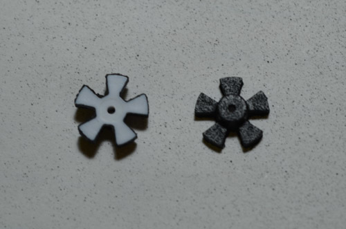
I am using Polou’s 5v optical encoder kit in both a Zumo chassis and in a round robot chassis. In the Zumo, I was able to use a single channel directly to the interrupt pins on my Arduino Uno. This did not work on the round robot. The signal was not big enough. One way to solve this is to use comparators. You get a nice square signal. I then discovered that when you take the encoder wheels off the shafts of the round robot motors, the peak (black) signal was considerably higher than with the encoder wheels present. Putting a black box around the two encoders to simulate the Zomo situation helped a little. Thinking that this lower signal was caused by reflections off the encoder wheels themselves, I painted all wheel surfaces except the one that the encoders use. This improved the signal by one whole volt.
My suggestion is to make the wheels that way. I have attached some photos.
Let me know what you think.
Hello.
Thanks for posting about your experience with our optical encoder kit! Unfortunately, a modification to the product like that would be very complicated, but we will keep it in mind, and it should be easy for others to paint them like you did if they want.
By the way, was the gap between the sensor and the white encoder wheel face consistent between the waveform captures?
-Jon
Hi Jonathan,
Thanks for your reply. Looking at the photos in my original post, I looks like the wheels were not in the same position.
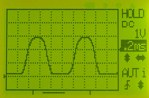
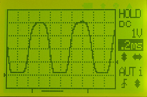
I do not have any unpainted five spoke wheels, so I did the following experiment with a three spoke wheel.
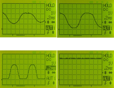
Look at the photo below, from left to right and top to botton.
The first photo is with the wheel as far away from the encoder without falling off the shaft.
The second photo, it is a little closer.
The third photo, it is just about right. The forth photo is with the wheel removed.
The point I am trying to make is that with the wheel on the shaft in any position, I cannot achieve a 4v high output, yet with a painted wheel that has narrower gaps between spokes, I do achieve it. There must be some surfaces on the wheel that are providing some low ambient light form the IR source. That’s what the paint is eliminating.
What do you think?
Ray
I think your experiment is pretty convincing; it makes sense that those white surfaces were reflecting IR like that. Good idea to paint them black; thanks again for sharing!
-Jon
Hi,
We tried this technique of painting the blades black and we are seeing the output of the encoder higher by almost 1.2V.
Also now the encoder is a little less forgiving to the distance between the tallest component and the blade.
I would say this is easiest if there is no time to add a comparator circuit.
Thanks,
Sharwari
@JonathanKosh,
I assume that the wheels are injection molded? Couldn’t you get the same effect of diffusion by simply sandblasting the interior of the mold, adding a slightly diffuse surface rather than the reflective black you get by default?
(I guess another option would be to soak them all in some mild chemical etch, but that’d be both messy, hard to time right, and create a waste disposal problem…)
Hi, Sharwari.
Thanks for letting us know how it worked for you. It seems like you meant to say the encoder wheel is now “more” forgiving (not less). If not, could you clarify how the encoder wheel is now a “little less forgiving”?
@jwatte:
Thank you for your suggestion. It is not clear to us that changing the encoder wheel texture will have much of an effect on reflections from the sides and backs of the wheel blades. If the readings are consistently low, one easier way to address that might be to add external pull-up resistors to raise the entire signal. In some cases, the built-in pull-up resistors on many MCU I/O lines might be enough.
-Jon
Physically, the small bumps reduce the angle of incidence where simple reflection will happen, because it creates multi-bounce which absorbs more of the light energy for shallow angles of incidence. Thus, the total energy reflected is reduced.
I apologize, I do mean more forgiving.
If the gap between the wheel and the sensor is slightly more than 0.5mm, signal amplitude is still within the VIH level of the micro with the black blades.
BTW, we are observing that there is a stop on the blades which does not allow them to be pushed down on the motor shaft beyond a certain point.
But with this the distance between the wheel and the sensor is actually more than 0.5mm.
Not sure if others have seen this?
Thanks,
Sharwari
@jwatte:
While I believe that sand blasting the mold might decrease total reflection, it is not obvious that total reflection is the problem. For example, maximizing total reflection by making the sides and back perfect mirrors might make the problem go away. It is possible that by sand blasting, total reflection will go down while light reflecting back to the sensors will actually go up, since it would function less as a perfect reflector and more as something that creates a diffuse glow.
@Sharwari:
There is no built-in stop on the encoder wheels. If you push hard enough on them, they should butt right up against the sensors on the encoder board in a way that would be damaging if power was supplied to the motor. It might be that since there is more material surrounding the motor shaft, it seems harder to press against. You might find it helpful to repeatedly remove and insert the wheel back-end-first to loosen up that part of the through-hole, which could make it easier to adjust the depth when you put the wheel back on normally.
-Jon
I suppose that is possible. I’m thinking about the statement in this thread that matte black paint improved the performance.
You could empirically try it. Blast the molds, and if it doesn’t work, just pay for new molds – can’t be more than a few thousand dollars each? 
