I have just started with electronics and still have a lot to learn, maybe this is too much to start with but am willing to learn how it all works. I have a few questions after I have read the entire user manual.
I have made the controller work on USB and on one power supply (5v 2A) (soldered wire from VIN to positive rail of the servo’s) I also saved a script that works in the controller, so It works like this.
Next I wanted to attach NO/NC switches to the board to have a trigger for the servo’s. A section in the user guide how this should be done, but it’s not clear enough to me. Before we mess things up I want to understand how it works.
In the example I should place a pull-up resistor 1-100Kohm(a)(b) and attach it to the signal pin of a free channel. on that pin you place the C of the switch and the NO or NC (what you want to make a full circuit depend on how you place the switch starting position) contact on the gnd of that channel.
Now I want to attach three NO/NC switches one after the other so that all need to be triggered before the servo’s start operating.
I tried searching on google and your forums if someone else already done this configuration but I cannot find any resources on this, or nobody is willing to share their projects.
(a) I cannot find anywhere exactly what kind of resistor this is. does this mean a resistor between 1 and 100Kohm? or does it mean 1w 100Kohm? Or do I need to look at the switches to determine the right Ohm resistor to place? (the store I bought the controller from only sells 1/4w, 1/2w and 1w resistors (but only the 1/4w and 1/2w ones come in flavor 100Kohm.)
(b) I have read into pull-up and pull-down and it’s a term of speech (resistor is just resistor) helping to let others understand your circuit schematic.
Can you help answer my question so I can have servo’s start operating after three switches are triggered?
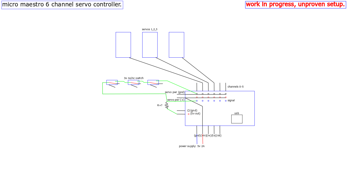
I’ve added an image of what I want to make.
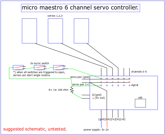
The 1-100 kΩ you mentioned is suggesting a resistor with a value of anywhere from 1 kΩ to 100 kΩ. Something in the range of 10 kΩ would be a good choice. Since there should be very little current through the resistor, you do not need anything special in terms of wattage.
It looks like you have your pull-up resistor connected correctly in your diagram. I’m not sure what your plans are for the switches, but the way they are connected right now, they would all need to be pressed to allow the voltage to reach the Maestro’s signal pin (e.g. you would not be able to detect a press on one or two of them independently). If you instead want each switch to function independently of the others, you would need to use a separate Maestro channel and a pull-up resistor for each. Also, please note that you should make sure the Maestro channels that the switches are connected to are configured as inputs in the “Channel Settings” tab of the Maestro Control Center.
Ok so it doesn’t really matter 1/4w 1/2w or 1w. IMO it would be helpfull to include that in the guide.
The reason I want three switches is that all need to be pressed. I am making a homemade pinball machine and these servo’s are going to be the reset function for three drop targets.
In the software I reserved the pins 0 to get the input. just like in my drawing. (not servo mode in software)
If this works the software then knows when you have hit all targets, and after some time-out period the servo’s should reset the targets and wait for the next cycle.
There is a video on youtube that is similar to what I am making.
That looks like a fun project! I don’t see any problems with your schematic (it should have the behavior you described). If you are willing to share more about your project when it is done, you might consider posting about it in the “Share your projects” section of our forum. I am sure other members here would be interested in it too.
Any resistor value between 1kΩ to 100kΩ should work fine in most cases. When using higher values the pull-up could be more susceptible to noise or interference. As far as power, a 1W resistor is overkill (but shouldn’t be a problem). Since it is just a pull-up resistor on a signal pin, there is very little current passing through it. If you wanted to go as far as to calculate the power, you can use Joule’s law combined with Ohm’s law since it is a resistive load:
it’s on a 1w 100K ohm resistor. altered the script to reflect the changes and now the servo’s move as the switch is released. the servo’s keep running their routine to the end if the switch gets interrupted, if the switch stays open the servo’s do another routine to get it closed. Just what I was looking for!
I will place a video on youtube when the housing for the drop targets are done and complete!