
Hello, I am hooking up a momentary relay via remote to start the sequence- but the resistor value (between the signal line of that channel and 5 V) - does that mean that the servo has to be in parallel to this switch?
Secondly- the doc says the range is between 1 - 100 K- does anybody know the right value? I don’t have a pot to test it- but is this so variable that I have to test it with a pot?
Hello.
It sounds like you are referring to the pull-up resistor described in the “Button or switch” heading in the “Attaching Servos and Peripherals” section of the Maestro user’s guide. This resistor is used to pull the voltage on the signal pin high when the button is disconnected, and when the button is pressed, it can safely connect the signal to ground. The servo should not be in parallel to the switch since the only common node they should share is the ground connection (e.g. the servo should be powered from a separate power supply and on a different Maestro channel). Please note that the Maestro channel that the switch is connected to should be configured as an “Input” in the “Channel Settings” tab of the Maestro Control Center. The value of the resistor can be anywhere from 1k to 100k; we typically use 10k.
If you have concerns about how you are connecting your switch, you can post a diagram or pictures of your setup, and I would be happy to take a look.
Brandon
Hi, Brandon,
Yes, I attached a photo. I am using a remote RF momentary switch. The magnetic relay (miniature Military grade) is shown below the Maestro. The 2 wire leads sticking up are non-voltage isolated circuit closure contacts generated from RF unit at top right. I have the 100K resistor in there now, but I will change it to the 10K.
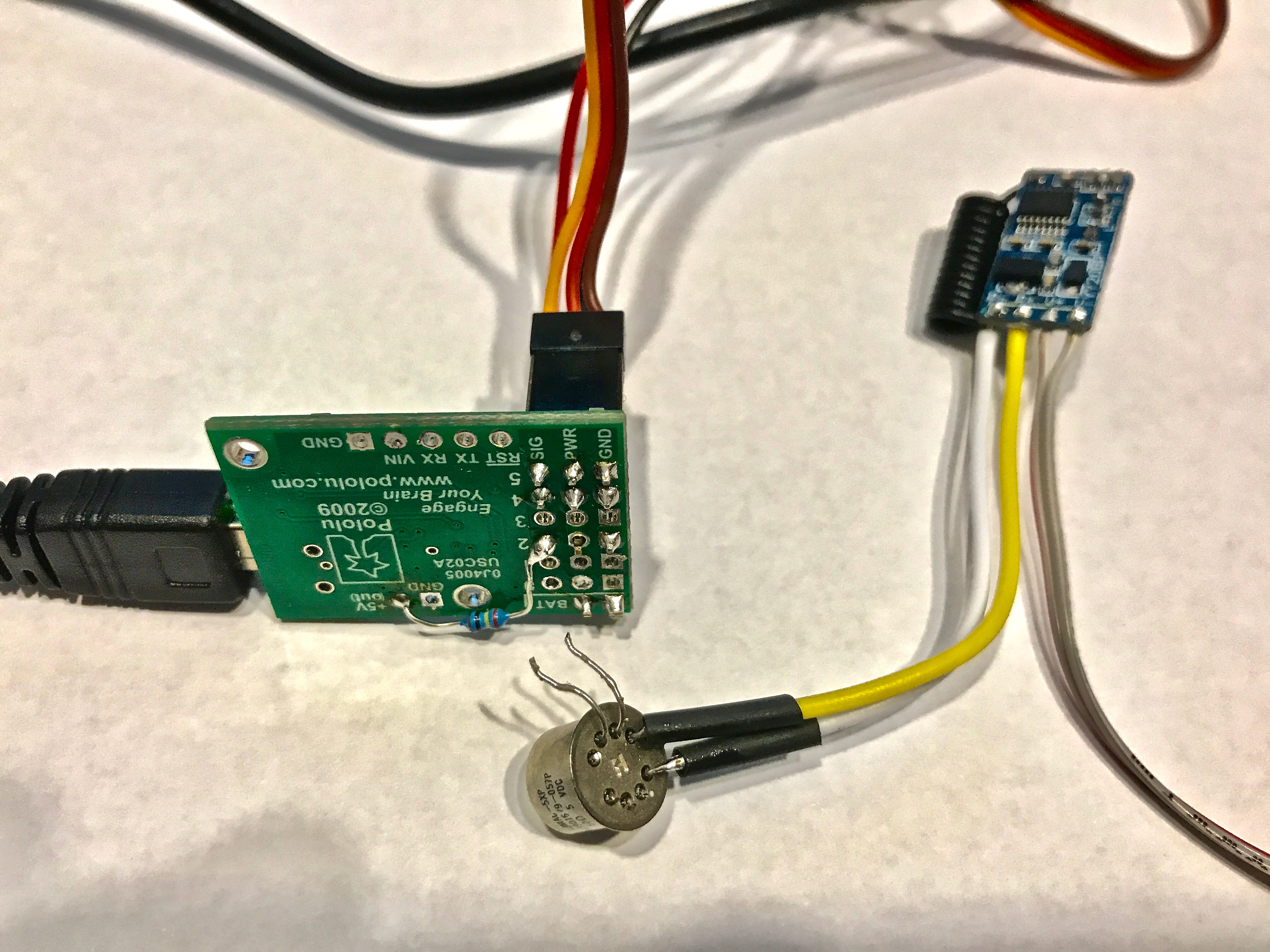
If your RF switch and magnetic relay work like a standard button (e.g. triggering the switch will close the two contacts, connecting the signal pin on the Maestro to ground), then that should work fine.
Brandon
Hi, Brandon,
I had to make some changes and I think I erased the chip, is I can’t seem to get the firmware or script back into the controller. I tried to rewrite the code the controller is not acting correctly anymore.
I will try to call you for a quick fix
Thanks,
Kelly
I spoke with you earlier today and we resolved the problem, but for anyone else on the forum, we were able to get the script working again by reloading an earlier settings file and working from there.
Brandon