
Hello, Tomek.
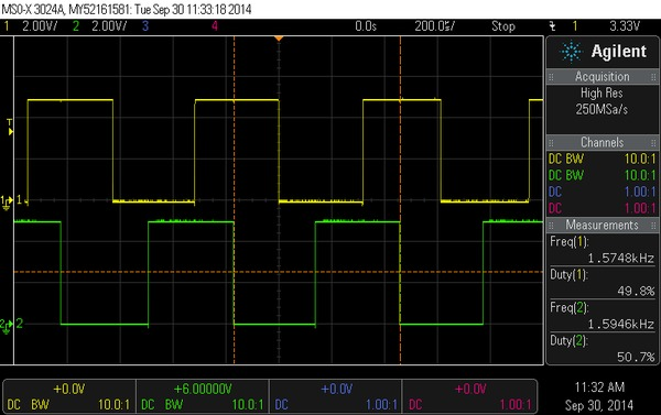
The phototransistor resistance goes down as the intensity of the incident IR goes up, so high reflection results in a low signal and vice versa. The low amplitude of your channel 1 signal makes it seem like that particular sensor is seeing a lot of ambient IR or, more likely, unintentionally reflected IR from one or both of the emitters.
Your latest scope capture makes it seem like you are making progress (thank you for posting those, by the way; it makes troubleshooting so much easier!). Note that these optical encoders are just providing the raw output from phototransistors, so the signals you get are highly dependent on how they are mounted relative to the encoder wheel. They are intended to be mounted directly on the back of the motor with the encoder wheel at a precise distance away. This yields decent results, as you can see on the product page, but even then we recommend you use intermediate electronics to condition the signals before passing them to a microcontroller. It sounds like you are trying to make it work in some alternate configuration, in which case it is even more likely you’ll need some kind signal conditioning between the encoder and the digital system reading it. Can you post some pictures that show how you are trying to set it up?
By the way, you might be interested in the magnetic quadrature encoders for micro metal gearmotors we released yesterday. They use Hall Effect sensors that output conditioned signals (with hysteresis) that can be connected directly to a microcontroller:
For more information, see Jan’s blog post about them.
- Ben