Micro-encoder can you help me understand the scope capture?

Hi!
So I have a scope capture (crudely taken with a photo of the DSO scope…just got the scope recently and haven’t a way to install the software yet [no cd-rom drive].)

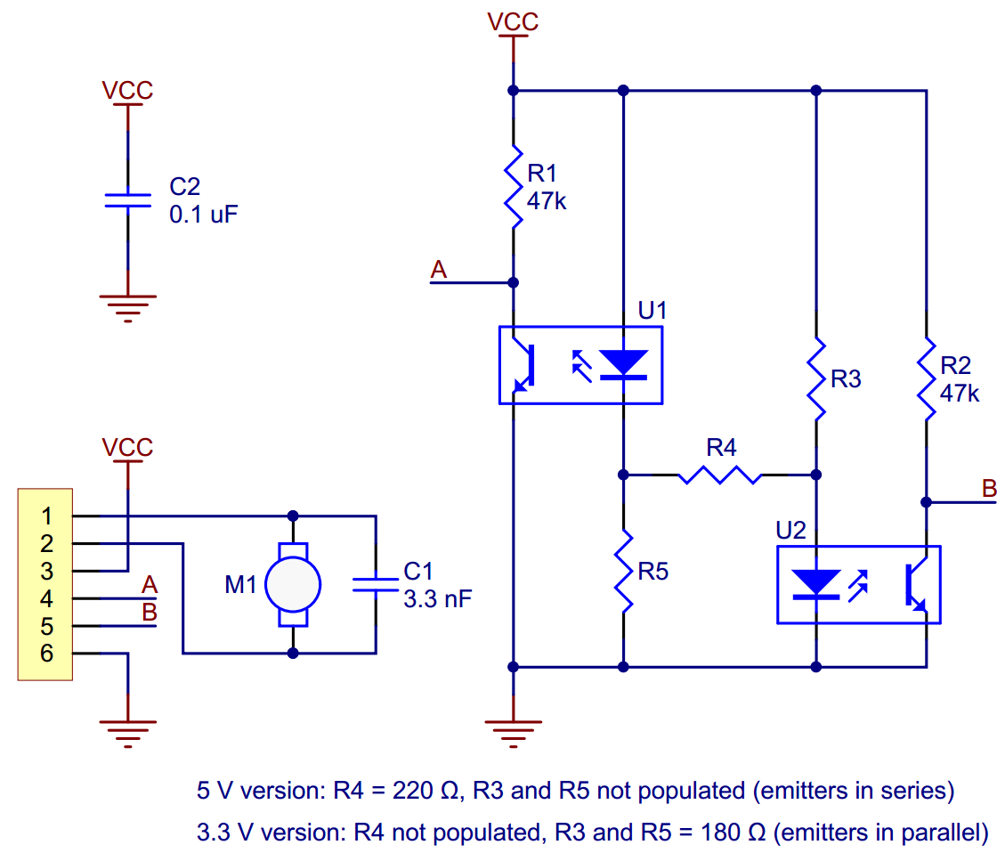
The capture is of the waveform of the two channels of a 3-star (there are 3 and 5 stars in the kit) equipped pololu micromotor encoder. Both channels are scaled to 500mV/block


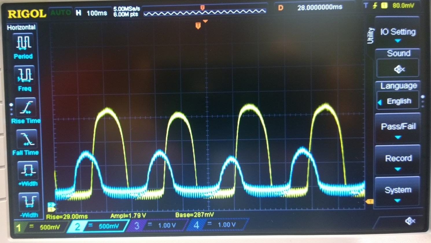
So there are a couple things that I can figure out from the scope. (1), is that it seems one of the 3 fins are slightly farther away from the sensors than the other 2. I say this because the peak on both signals is slightly lower for one of the 3 peaks, and I interpret this to mean the reflectance of the IR led is less, so either the fin has less reflectance because the surface is marred physically, or it’s bent slightly backward. I hope this is a proper reasoning [not just me not knowing how things work.]

I also believe that my signals vary from the example pololu encoder signals insofar as they have a longer dead period, because the examples are all of the 5-star encoder wheel, not the 3-star encoder wheel. I hope my 3-star vs 5-star naming scheme has been clear (5-star meaning five-point star.)

Anyway, what I’m still trying to work out is why one of my signals is much weaker than the other. One signal seems to be about 0.8V, and the other signal looks to be a much heartier 1.8 ish Volts. 1.8V is clearly in the territory of a HIGH on my 3.3v teensy 3.1 MCU, but 0.8V is slightly sketchier. But why would one sensor read such a lower value than the other? Could it be a smudge on the sensor or something? It is normal intrinsically to the sensor?

To be honest, I don’t know exactly what will trigger an interrupt on the teensy. Following the datasheet, a “HIGH” is 0.7Vdd, so 2.31V. That said I think that’s the HIGH that is produced by the MCU, not what triggers an interrupt using the quadrature encoder library. In fact, it seems to be working O-K, to be honest. So I imagine a HIGH can be triggered in the 0.6-0.8V range, OR, I’m running the encoder with only one output unbeknownst to me. Because the gearing of my system is a little unknown (random parts), I can’t easily figure out if the second output is working.

Eventually I plan on adding a comparator. It seems to me the examples say to calibrate to 50% duty on the signal, but that i could get away without doing that, so long as my interrupts can be handled fast enough even if the signal is 25%/75% (i.e, that the reason for calibrating to 50% is just so that you are HIGH as much as you are LOW, but I don’t know why else the comparator is used in that fashion.)

Thanks for any help. I appreciate learning more about this stuff, but I’m still ME and just learning.

Been fiddling some more around, and definitively of the conclusion I need some help to know what I’m doing. I went to the schematic and found this image:

So the thing is I’m a little concerned I don’t know what the schematic is saying.

what I thought:
Diode makes light, photoreceptor produces voltage in response. Photoreceptor gets light from the bouncing of the diode light against the star-fin-thing. When there is nothing in front of the photoreceptor, there’s not enough light to make a good signal. Voltage is the peak I’m seeing.

what the schematic looks like:
It looks like more like a opto-gate sort of thing, not sure exactly the terminology. Looks like the signal is pulled up to Vcc (3v3), and then when the photoreceptor gets a sufficient light reflection, it opens the gate and pulls down the signal to zero volts.

In that case, I should totally be getting 3V3 for most of the time, then near 0v whenever the gate is pulled down. It’s neither what I’m seeing, nor what the example scope graphs seem to suggest. EDIT: I think maybe I was reading the gate wrong. It might be such that the light turns OFF the gate, and the signal then should be 3.3V whenever I have reflected light. Still, I see much less than 3.3V. does that mean I need the fins closer to the sensor or something?

Can anyone clarify my understanding? Let me know if I haven’t been clear in presenting or posing the questions.

Thanks!
-Tomek

New scope capture!

By shifting the sensor up, I got a better signal. My application doesn’t have the board directly on the back of the motor (that was just for testing), but on the opposite wall opposing a gear that has the star-fin thing on it. So in addition to the Z-direction along the axis of the motor/shaft business, I can also mess up my alignment on the X-Y pretty easily :).

This capture looks much better, in the healthier 1.2V+. Not great but not bad.


Hello, Tomek.

The phototransistor resistance goes down as the intensity of the incident IR goes up, so high reflection results in a low signal and vice versa. The low amplitude of your channel 1 signal makes it seem like that particular sensor is seeing a lot of ambient IR or, more likely, unintentionally reflected IR from one or both of the emitters.

Your latest scope capture makes it seem like you are making progress (thank you for posting those, by the way; it makes troubleshooting so much easier!). Note that these optical encoders are just providing the raw output from phototransistors, so the signals you get are highly dependent on how they are mounted relative to the encoder wheel. They are intended to be mounted directly on the back of the motor with the encoder wheel at a precise distance away. This yields decent results, as you can see on the product page, but even then we recommend you use intermediate electronics to condition the signals before passing them to a microcontroller. It sounds like you are trying to make it work in some alternate configuration, in which case it is even more likely you’ll need some kind signal conditioning between the encoder and the digital system reading it. Can you post some pictures that show how you are trying to set it up?

By the way, you might be interested in the magnetic quadrature encoders for micro metal gearmotors we released yesterday. They use Hall Effect sensors that output conditioned signals (with hysteresis) that can be connected directly to a microcontroller:

For more information, see Jan’s blog post about them.

- Ben

Yaaay! I’m ordering right away. This was a long time in coming. I have the plastic wheel/optical encoders of this thread, and they are less than ideal.

Will there be a 3Pi featuring the magnetic encoders?

Hi, Jim!

Thanks a lot for your enthusiastic “Yaaay!” In case you didn’t see it, you might be interested in my blog post about our progress with encoders over the years:

pololu.com/blog/414/new-prod … gearmotors

There isn’t anything as specific as a “3pi with encoders” in the works yet, but I definitely hope to develop some round robot with encoders some day. There’s still a lot to figure out, like what to use for a processor (the ATmega328 we have on the 3pi doesn’t have the available I/O) and whether we should make a round, wheeled robot with encoders before we make a square, tracked robot with encoders.

- Jan

Jan -

I did read the blog. I’m impressed by the careful work, and especially that you can offer the encoder at such an great price!

I just bought a 256 stripe, ball bearing Bourns shaft encoder (ENS series) to use as a wind direction gauge on an autonomous sailboat. It is lovely but the lowest price I could find was over $50 at Digikey.

Cheers, Jim

Thanks for all the responses! I really appreciate them.

Jim, one thing I’ve found for one-off projects has been that ebay often has used quality equipment for cheap. It’s never a source that is reliable for long-term, but when you just need “some quality Maxxon with an insane encoder” you can often pickup for $20 what retails for $200++. This is just basically scrappers who take apart or somehow source cheap post-industrial use motors. When it was originally a quality product it often has a lot of life left in it. Just a general thought outloud.

Ben,
I really appreciate your response! I definitively really appreciate having a better understanding of what was happening, since you could see as my posts progressed I was only barely working it out. I think I understand now the situation, and take that the gate lowers its resistance as the IR light increases on the receptor. The fact that I never get a full 3.3V signal suggests that the gate always stays a little open whether by incident light or just the default state itself. I still don’t quite understand schematic notation, but the triangular down-arrow made me think that it was somehow working in reverse. That is, that without a signal it would be pulled down (and in this case you are saying with a signal it is pulled down.) Anyway, now I’ll take your word that it works that way, and try to review sometime how gates/transistors are notated on schematics. More to learn, more to learn, haha.

I was actually very interested in the encoder you came out with the other day. I noticed it while I was especially struggling with the problem here and just browsing pololu new products and the forums. I think you could see how while I was hoping to hear back on my post here, I was basically perusing and trying to answer a few questions on the forum that I could answer. It’s a great method you have here for product support, because the majority of my questions are already asked and answered here on the forums. Plus, I end up getting input from other knowledgeable users in additional to pololu staff (thanks Jim.) And then, hopefully, I can sometimes give back to that karma circle [tends to be in impulses coinciding with whenever I’m stuck with my own projects.]

The way I put together the current setup, I’m not sure if I am going to be able to fit the newer slightly sticker magnetic disk. It’s a unfortunate, because it’s quite tantalizing to have the cleaner signals. I will for certain order some of the boards to test out, but I dont know if I can adapt my current project to use them (such is life.) The hysteresis bit is nice too, but in my code I’m only paying attention to my encoder signals when I’m moving so I dont think I’ll have major problems with being stuck on a threshold or anything like that. I’m making a rev2 of my board that these parts plug into and now basically I need to decide whether or not to include the comparators for better signal processing. But then if I do, it’ll mean I need to make a Rev3 if I ever make more of these and use the magnetic boards :p. I can see how you have to constantly make compromises in these sort of situations, I’m just not yet certain how I’ll go with this one. Maybe I’ll try to do something that I can add the comparators or not include the parts if I want to bypass them.

Hi Jan,
thanks as well for your response. Similarly, I enjoyed reading the post with details behind the new improvements.

Update! I tuned in the optical sensor setup, before eventually tugging the wires a little and bringing it out of its good position [Since I had only used double-sided sticky tape to secure the board.] Optical solution = usable, but tricky when you can’t mount it directly on the motor shaft (where I initially did most of my testing before this thread.)

but this is actually a positive post
The magnetic encoder kicks ass. I switched over to the magnetic encoder, and besides clean signals by nature, the magnetic encoder is great in two ways

(1) much less sensitive to wheel&encoder alignment. The alignment right now isn’t even perfect, and the signal is still quite good enough for my application.

(2) The board is better designed this time. I admired how the optical encoder looked to be made with a half-hole fully plated side-connection for the wires that connect to it, as in I think it was clever, but they were just far too finicky to solder thin wires to. The new board managed to be made with proper complete holes on the edge, and its just much easier to solder to. It also has a good silk screen which helped me double check the connections.