
Been fiddling some more around, and definitively of the conclusion I need some help to know what I’m doing. I went to the schematic and found this image:
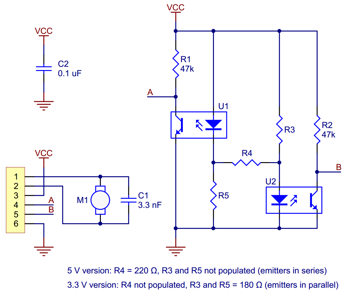
So the thing is I’m a little concerned I don’t know what the schematic is saying.
what I thought:
Diode makes light, photoreceptor produces voltage in response. Photoreceptor gets light from the bouncing of the diode light against the star-fin-thing. When there is nothing in front of the photoreceptor, there’s not enough light to make a good signal. Voltage is the peak I’m seeing.
what the schematic looks like:
It looks like more like a opto-gate sort of thing, not sure exactly the terminology. Looks like the signal is pulled up to Vcc (3v3), and then when the photoreceptor gets a sufficient light reflection, it opens the gate and pulls down the signal to zero volts.
In that case, I should totally be getting 3V3 for most of the time, then near 0v whenever the gate is pulled down. It’s neither what I’m seeing, nor what the example scope graphs seem to suggest. EDIT: I think maybe I was reading the gate wrong. It might be such that the light turns OFF the gate, and the signal then should be 3.3V whenever I have reflected light. Still, I see much less than 3.3V. does that mean I need the fins closer to the sensor or something?
Can anyone clarify my understanding? Let me know if I haven’t been clear in presenting or posing the questions.
Thanks!
-Tomek