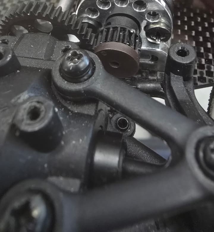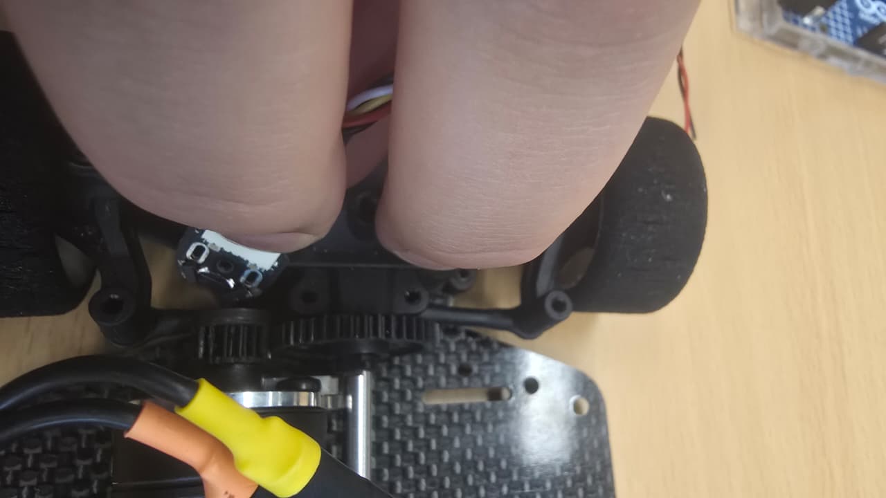


Good day everyone,
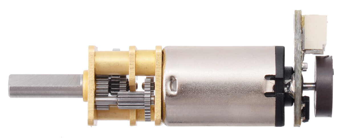
I am facing a weird problem with my Pololu magnetic encoder.
The problem is that I am currently trying to read it on my Arduino UNO R4 Minima; however, the output stays stuck at 1 and does not want to toggle into the usual quadrature format.
Here is the code I am using:
// Quadrature (Pololu 4761) on A=D2, B=D3 → RPM + speed (m/s) + distance (m) + ESC ramp
// Serial Plotter columns: A, B, rpmQuad, speed_mps, dist_m, ESCuS

#include <Arduino.h>
#include <Servo.h>

#ifndef IRAM_ATTR
#define IRAM_ATTR
#endif

// -------- Pins --------
const uint8_t pinA   = 2;    // External interrupt pin
const uint8_t pinB   = 3;    // External interrupt pin
// -------- Your empirical calibration --------
const float COUNTS_PER_METER = 615.0f;          // <-- your measured value
const float METERS_PER_COUNT = 1.0f / COUNTS_PER_METER;

// (Optional) keep RPM too. If unknown CPR, this is just "effective RPM" vs. your earlier assumption.
// If your encoder really is 12 counts/rev at 4x on the motor shaft and you're on the wheel, CPR_QUAD should be "wheel counts per wheel rev".
// You can ignore RPM if you only care about speed & distance.
const int CPR_QUAD = 12;  // keep as-is if you want RPM; otherwise you can delete all rpm code


// -------- Quadrature state (ISR) --------
const int8_t qtab[16] = {
  0, -1, +1,  0,
  +1, 0,  0, -1,
  -1, 0,  0, +1,
   0, +1, -1,  0
};

volatile long     q_count = 0;           // signed tick count
volatile uint8_t  q_prev  = 0;           // previous AB state
volatile uint32_t q_lastEdge_us = 0;     // for minimal deadtime
const uint16_t    q_dead_us = 10;        // ignore transitions arriving <10us apart

// -------- Kinematics computation (loop) --------
float rpmQuad = 0.0f;                    // signed RPM (optional)
float speed_mps = 0.0f;                  // signed linear speed (m/s)
float distance_m = 0.0f;                 // signed odometer (m)

const float rpmAlpha   = 0.9f;           // EMA smoothing for RPM (responsive)
const float speedAlpha = 0.5f;           // EMA smoothing for speed (moderate)

uint32_t  sampLast_us  = 0;
long      sampLast_cnt = 0;
const uint32_t SAMPLE_US = 25000;        // 25 ms window (~40 Hz updates)

// -------- Plot timing --------
const uint32_t PLOT_HZ = 100;
uint32_t lastPlot_us = 0;

// ==================== ISRs ====================
inline void quadStepFromAB(uint8_t A, uint8_t B, uint32_t now) {
  if ((now - q_lastEdge_us) < q_dead_us) return;  // deadtime

  uint8_t curr = (A << 1) | B;
  uint8_t idx  = (q_prev << 2) | curr;
  int8_t step  = qtab[idx];
  if (step) {
    q_count += step;
    q_lastEdge_us = now;
  }
  q_prev = curr; // keep state updated
}

void IRAM_ATTR isrA() {
  uint32_t now = micros();
  uint8_t A = digitalRead(pinA);
  uint8_t B = digitalRead(pinB);
  quadStepFromAB(A, B, now);
}

void IRAM_ATTR isrB() {
  uint32_t now = micros();
  uint8_t A = digitalRead(pinA);
  uint8_t B = digitalRead(pinB);
  quadStepFromAB(A, B, now);
}

// ==================== Helpers ====================

// Compute RPM (optional), speed (m/s), and distance (m) from delta counts over SAMPLE_US
void updateKinematics() {
  uint32_t now = micros();
  if ((now - sampLast_us) >= SAMPLE_US) {
    noInterrupts();
    long cnt = q_count;
    interrupts();

    long dcnt = cnt - sampLast_cnt;        // signed counts in window
    uint32_t dt_us = now - sampLast_us;    // us
    float dt_s = dt_us * 1e-6f;

    // ---- speed (m/s) from your counts-per-meter ----
    float inst_speed = (dcnt * METERS_PER_COUNT) / dt_s;  // signed m/s
    speed_mps = speedAlpha * inst_speed + (1.0f - speedAlpha) * speed_mps;

    // ---- distance (m) integrate counts ----
    distance_m += dcnt * METERS_PER_COUNT; // signed odometer

    // ---- RPM (optional) if CPR_QUAD is set meaningfully ----
    // RPM = (counts / CPR) * (60 / dt)
    float inst_rpm = (float)dcnt * 60.0f / (float(CPR_QUAD) / dt_s); // same as 60e6 / (CPR * dt_us) * dcnt
    rpmQuad = rpmAlpha * inst_rpm + (1.0f - rpmAlpha) * rpmQuad;

    // advance window
    sampLast_cnt = cnt;
    sampLast_us  = now;
  }
}

void plotNow() {
  const uint32_t now = micros();
  const uint32_t interval = 1000000UL / PLOT_HZ;
  if (now - lastPlot_us >= interval) {
    lastPlot_us = now;
    int A = digitalRead(pinA);
    int B = digitalRead(pinB);
    Serial.print(A);              Serial.print('\t');
    Serial.print(B);              Serial.print('\t');
    Serial.print(rpmQuad,   1);   Serial.print('\t');   // optional
    Serial.print(speed_mps, 3);   Serial.print('\t');

    // Changed to println() and removed the trailing tab
    Serial.println(distance_m, 3);
  }
}

void rampUpAndDown() {
    updateKinematics();
    plotNow();
    if (Serial.available() && (Serial.read() == 'z')){Serial.print("Serial Problem");}
}

// ==================== Setup / Loop ====================
void setup() {
  Serial.begin(115200);

  pinMode(pinA, INPUT);  // Pololu board has pull-ups to its VCC
  pinMode(pinB, INPUT);

  // Initialize previous state
  q_prev = (digitalRead(pinA) << 1) | digitalRead(pinB);

  // Attach CHANGE interrupts on both channels
  attachInterrupt(digitalPinToInterrupt(pinA), isrA, CHANGE);
  attachInterrupt(digitalPinToInterrupt(pinB), isrB, CHANGE);

  // Initialize sampling
  sampLast_us  = micros();
  sampLast_cnt = 0;

  // Serial Plotter header
  Serial.println("A\tB\trpmQuad\tspeed_mps\tdist_m\tESCuS");
}

void loop() {
  rampUpAndDown();
}
And a quick image of my setup:
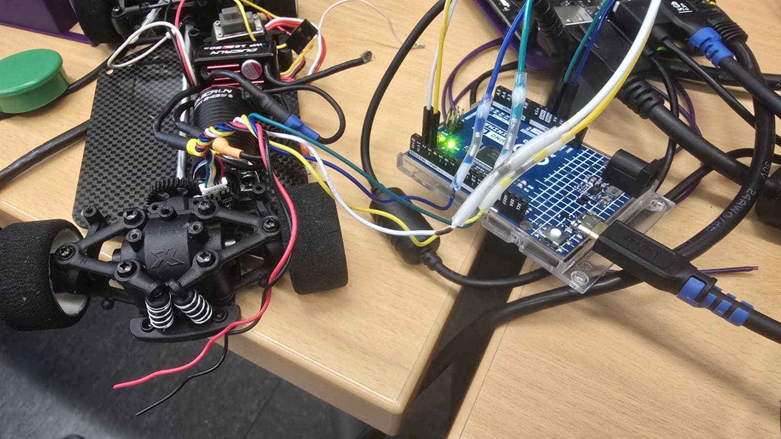
What’s weird is that this used to work before hand, but right now it is refusing to change.