Hi everyone, I have a maestro 12 channel controller, setup to use in my Ironman helmet, along with a hitek 645mg servo.
Basically what I’m trying to do is get some kind of braking system on here so that when the face plate of my helmet goes up it stops buzzing. Its buzzing cuz it’s trying to hold the face plate up, which isnt that heavy. I’m wondering if someone know’s how to rig up a magnetic breaking system that wouldn’t require opening the servo and soldering, I’m not really good with that and I’m kind of a beginner when it comes to this stuff. So when I read the descriptions to relays and all that I feel like my heads going to explode.
Is there a way to go from maestro --> relay --> servo?
I’m not sure I understand the braking system you have in mind; could you elaborate on it? Do you have an example of a similar system somewhere?
One alternative you might consider is switching to a stronger servo. I used some 1501MGs in an Iron Man helmet; it looks like they have about twice as much torque as the HS-645MG. I didn’t really have a problem with the servos straining or buzzing, though your results might depend on how your helmet is built and how heavy your faceplate is.
Hi Kevin thanks for the reply! There’s a guy from England that did this kind of breaking system but he added resistors or capacitors to a breadboard, and then re wires and soldered wires inside the servo.
There’s a video of how he does it, I’m wondering if pololu already has something like this but maybe in an easier more plug and play version. Mainly the parts where I get confused in the video are…
1, When I open my servo I don’t have a black and red wire, it’s orange and brown. I don’t know which one is ground or power.
2, I don’t know how anything about resistors or capacitors or how to wire them to a breadboard like he does in the video.
This looks like a relay he used in the video pololu.com/product/2804
But from the description I am not sure. Just wondering if there’s a way to use a relay with out having to open the servo and re solder the wires, so it shorts out the servo and causes it to “lock” into position until the button is flipped again.
Hope I gave enough detail with out confusing the heck out of you haha
For wire colors, if you’re referring to the three wires coming out of the servo:
Signal is usually white or yellow;
Power (+) is usually red;
Ground (-) is usually black or brown.
However, if you’re talking about the two wires connected to the motor terminals instead, it shouldn’t matter which one you splice the relay into; they should be interchangeable for this purpose.
You could certainly use our RC switch with relay, controlled by a servo channel from the Maestro. However, it would be just as easy to use one of our basic relay carriers and configure one of the Maestro’s channels as a digital output to control it. Either of those boards includes a circuit for driving the relay, so you wouldn’t need to make your own driving circuit like the one in the video you linked to. You would still have to open up the servo and solder in the relay connections, but at least you can then hook up the relay board to the Maestro directly.
That sounds like exactly what I’d like to do! I don’t suppose there’s a diagram on how to do this some where out there is there?
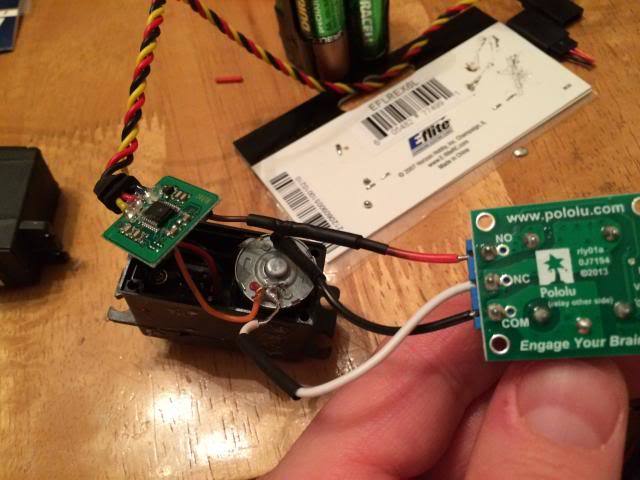
Yes, the wires connected to the motor terminal inside the servo are Orange and Brown. (From what you said I’m going to say that the brown is the ground) In that video he says to solder the brown to the orange terminal (in this case), then solder a wire from where the brown wire came from to the relay. (so my question about that is, those blue screw things on the board, are those what i screw the other end of the wire into? If so are they labeled + - Signal?)
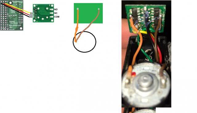
So I apologize for the crude drawing, but is this basically how to connect the (Basic Relay Carrier) relay to the maestro with a fem/fem connector?
If that’s right, then my question becomes how do i wire the servo to the blue screw thingies? I know that I wire the brown to the orange terminal on the motor, but then what?
What do I wire to these terminals?
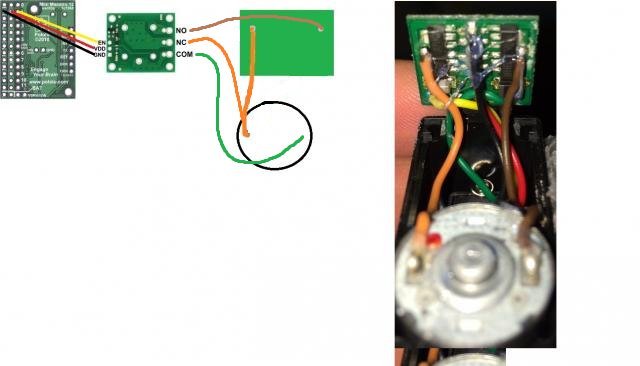
Your diagram is a little off. Here’s what it should look like:
The orange wire corresponds with the white wire in the video, and the brown wire corresponds with the red one. (I am talking specifically about the two wires connected to the motor; this correspondence might not hold for other wires.)
I’d like to explain what this is doing so that you understand what’s going on. First, you should understand how a relay works:
When the relay is not energized (its normal, default state), the relay’s COM (common) terminal is connected to its NC (normally closed) terminal, and NO (normally open) is isolated.
When the relay is energized, the COM terminal is connected to the NO terminal, and NC is isolated. On our relay carriers, the relay is energized when you put a high signal on the EN pin.
So when you connect the relay to the servo like this, the right motor terminal (green, COM) is connected to the left one (orange, NC) in the normal state, which brakes the motor. When you energize the relay, the right motor terminal becomes connected to the servo’s internal control board (brown, NO) instead, allowing the servo to be operated as usual. Does that make sense?
Kevin, thanks for the reply! It does make sense! (Though I had to keep looking at the picture then back at what you said) but yes I totally see what you mean now!
I’m going to order 5 relays and 1 of the servo’s that you mentioned, the https://www.pololu.com/product/1057 1501MG.
When I get this 1501mg servo, and open the back, do I need to make sure that there’s a wire going from the positive terminal on the motor to the NC on the relay? (Instead of the negative)?
Man, I cant really express how thankful I am, just saying you rock doesn’t do it justice!
As long as you keep everything else consistent, it doesn’t matter which motor wire is which (there isn’t really a positive and a negative motor wire; the direction of the voltage and current depend on which way the motor is turning). As long as you
keep one side of the motor connected to the servo board and also connect that to NC
connect the other side of the motor to COM
connect the other output of the servo board to NO
it should work.
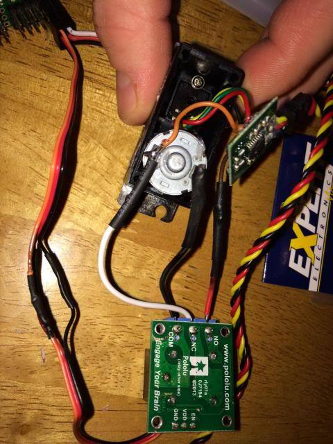
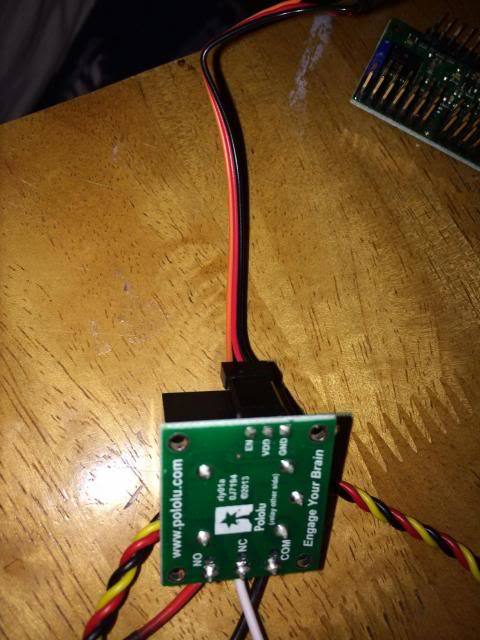
If you have any trouble or if you want me to double-check your connections before you apply power, post a picture of your wiring and I can take a look. Good luck and let us know how it goes!
So I think I have everything wired up right, I connect the relay to the maestro, and the relay to the servo, do I do anything with the cord coming out of the servo? Do I still keep that channel set to servo (in the maestro control panel)
Yep, both the relay and the servo should be connected to the Maestro. The channel the relay is connected to should have its mode set to Output (and the servo channel should remain Servo).
Hi Kevin, I finally had a chance to test this, and the good news is, the servo still works but the bad news is… is that it does not exactly work how I thought it would.
So I connected everything, and plugged in the USB to the pc running the control center, and I set channel 4 as an output and left everything else connected the same.
Default that channel that has the relay on it (ch 4) is set “Target” to 1500, if its set like this everything works as if there was no relay, and I stress the servo and it buzzes.
But then I take that target bar and slide it below 1500 and I hear the relay click and the buzzing goes away. But now the problem is that when the servo is stressed at all it slowly moves until I put the target above 1500 and then the servo snaps back to its original place of where it was before I put the slider below 1500 and it starts buzzing again.
Yes, that sounds normal. To make sure your connections are right, you can try using a multimeter to measure the resistance across the motor terminals: when the system is braking, the resistance should be very close to 0 ohms (since the terminals should be shorted together). You might want to disconnect the servo from the Maestro while you do this to make sure you don’t accidentally measure a powered portion of the circuit.
To be clear, you shouldn’t expect this type of braking to hold as strongly as (for example) a disc brake on a car or any other brake that uses friction to stop something from moving. The idea is that if you short a motor’s leads together, trying to spin it will make it act as a generator and create an electric current and magnetic field that opposes the rotation.
The video you originally linked demonstrates this briefly around 2:00. The motor doesn’t become impossible to spin, just harder. In the helmet, this should hopefully provide enough mechanical resistance to prevent the visor from falling down easily. Have you tried the system in your helmet?
I haven’t put it in my helm just yet, I’m still trying to figure out the source code to flip channel 5 to lower then 1500 when it finishes moving to its position. Its a little challenging. In a previous post you mentioned the Power HD High-Torque Servo 1501MG https://www.pololu.com/product/1057
I was wondering if you knew of a servo that is nearly as powerful but is slimmer? I ordered one of those, and I must say holy cow, that thing is strong, and it does not buzz at all! Which basically negates the entire thing I’m trying to do with the magnetic braking. That’s servo is boss. I am just wondering since I’ve never even heard of that kind of servo before, if you have any recommendations for a slimmer servo that is nearly as strong, it does not even have to be equal to that, I feel its way over powered for what I need which is certainly awesome! But if I can find a slimmer one that would be fantastic!
I thought magnetic breaking was a good idea, but a simpler idea is this…
I use 2 Hitec HS-82MG servos for my Iron Man helmets. When the animation for the faceplate is finished, program the servos to turn off. No more buzzing and the Metal Gear servos should hold up quite nicely. The only time I’ve had it move down on me was while dancing in the suit. A quick press off your button will get the faceplate down again and you can just open it back up.